

Cast-in-place & exposed concrete
Light lines that merge with the architecture. Whether exposed concrete or skim-coated ceiling: LightLineLed integrates the light into the surface and keeps the technology accessible for later service.
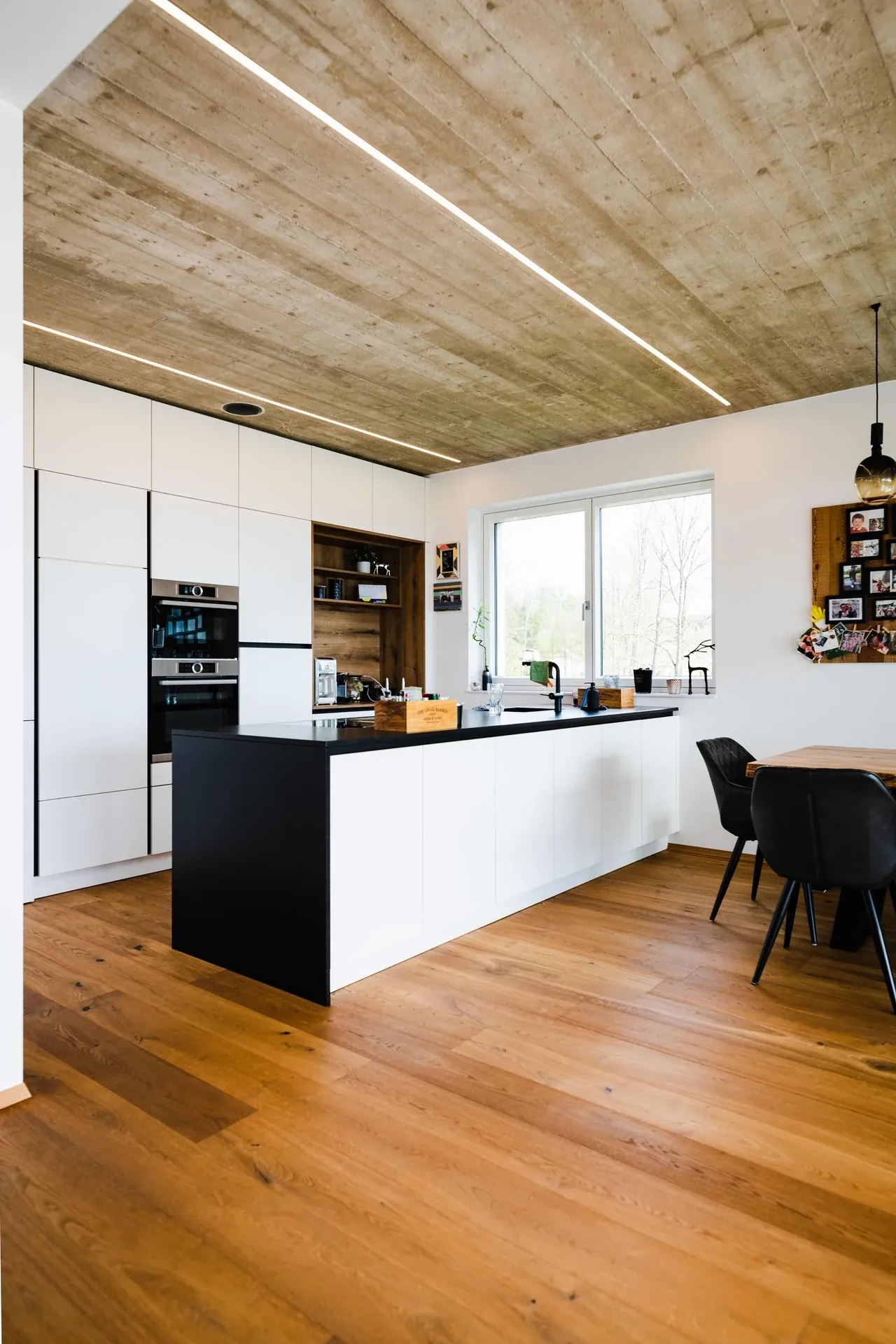
Concrete installation – how the light line is prepared in the concrete and integrated into the finished surface.
Watch on YouTubeWhat this solution makes possible.
The line of light begins already in the formwork. The recessed profile becomes a permanent part of the concrete; the prefabricated light insert is added after construction work. This keeps the visible surface clean and the lighting technology accessible for later maintenance.
A prepared system housing instead of chiselling work after the fact.
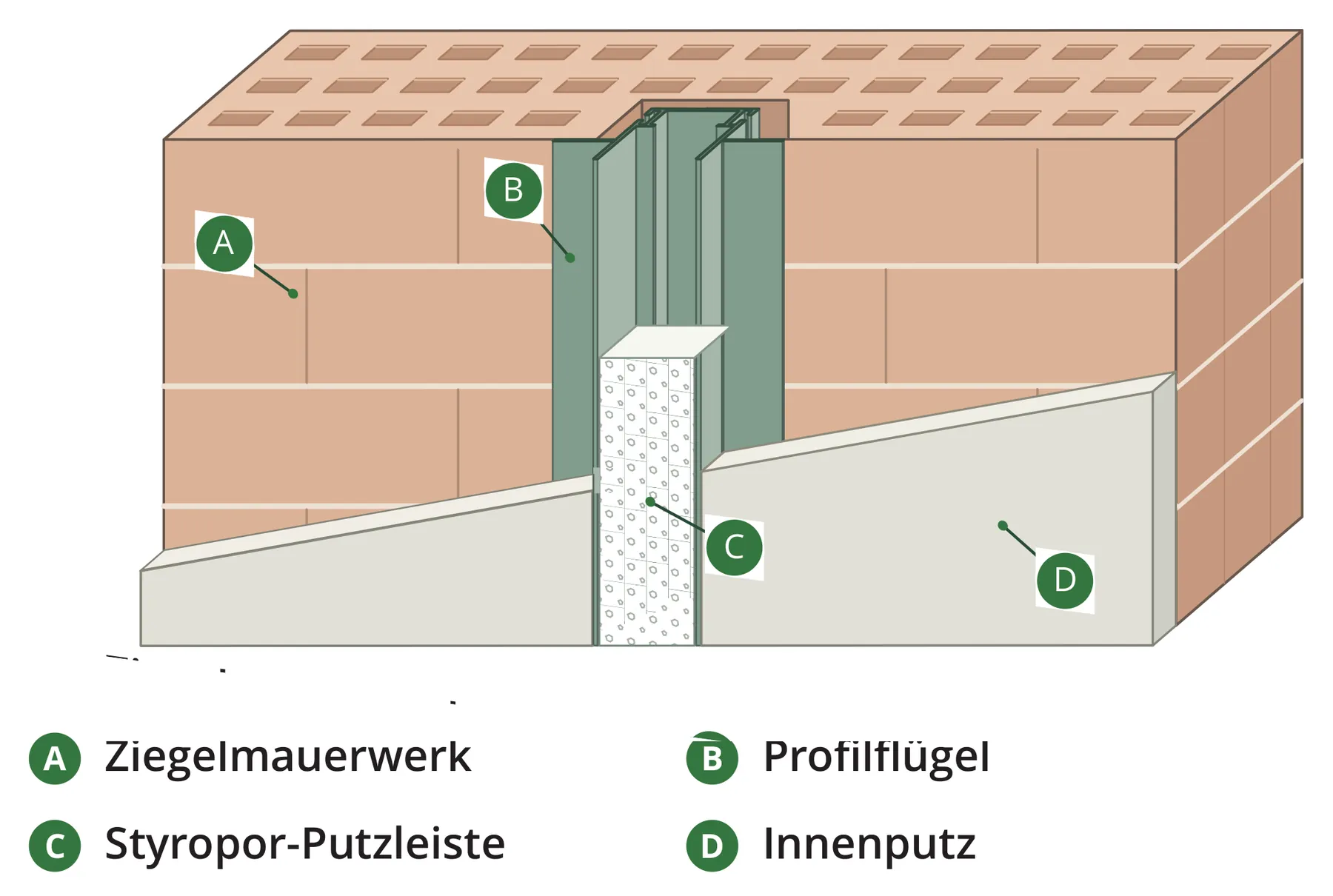
Exposed concrete, filled surface and interior plaster, each with the matching connection.
Mounting profile for the light line and a separate, accessible section for transformer and technology.
This is how your line of light is made.
Application, construction and benefits – tailored to your architecture.
Integrate light into the architecture from the start
With LightLineLed, the light line becomes part of the building as early as the concrete pour. The receptacle is created in the formwork and remains permanently in the ceiling or wall. This allows light paths to be planned together with room axes, furniture and circulation routes. In the finished room, the clear line takes centre stage: the embedded body sits in the concrete, while the visible profile and its cover form the desired light output. For clients and architecture, the result is lighting that deliberately belongs to the structure.
One system for exposed concrete, filler and plaster
The same system idea can be combined with different surfaces. With exposed concrete, the precisely prepared opening determines the finish. If the surface is to be filled or plastered later, suitable connection profiles create the transition between recessed profile and finished surface. This enables a consistent design even when different ceiling surfaces are used within one building. The sections show these differences: what matters in each case is the visible connection that suits the architecture and the intended surface build-up.
The technology gets its own place
The mounting profile and transformer profile fulfil different tasks within the same light line. The mounting profile receives the later luminaire insert; a deeper transformer profile section creates space for suitable control gear and connections. This allows the supply technology to be placed exactly where it is needed and remain accessible later. The position and size of this area are coordinated with the lighting design. The visible line can run continuously in design terms, even though housing and technical sections alternate behind it.
Fit late and stay accessible in the long term
The actual light insert follows only after the construction and surface work. The visible profile, LED strip and cover can be prepared and tested under clean conditions; sensitive components remain protected during the remaining work. Light colour and lighting effect can be assessed in the finished room within the prepared system options. The separation also offers an advantage later on: where a service access is provided, the suitable insert can be removed for maintenance or changes while the channel stays in the concrete. The profile run and technical room are coordinated early with the structural engineer for this purpose.
The solution in section
The system as construction progresses.
From the prepared housing to the finished light line.
The path to the finished light line
Coordinate before concreting
Define light line, finished surface, transformer position, cable route and reinforcement together. Do not alter reinforcement on your own authority.
Secure profiles on the formwork
Align the mounting strip, connect the profiles and fit the end caps. Check alignment and height; secure against floating up, twisting and shifting. Additionally secure end caps and concrete connectors with NewLuxLed fabric tape.
Strike the formwork and finish the surface
For exposed concrete, check the combination of drill hole and screw head on a sample: the screw should be pulled out in a controlled way with the formwork and timber strip. For filler or plaster surfaces, use the matching connection profile and protective strip.
Install the light only in the finished room
Remove protection, clean the profile channel and measure the fit-out height. Connect the prepared light unit, fit it with suitable safety devices and clip it in.
Installation & documents.
The installation and processing instructions accompany the actual implementation of your line of light.
In-situ concrete & exposed concrete · Installation & processing
PDF · matching instructions
Safety and installation notes
PDF · observe together with the instructions
The complete installation manual
All applications and system details
Processing notes in detailMounting clips, safety cable and further notes on the specific design
Build-up details
The opening faces the formwork skin. A matching timber mounting strip positions and stiffens the profile.
Mounting profile 37 mm, transformer profile 64 mm high. For electronics and terminal point, at least 50 cm of transformer profile; in practice usually 1 m, depending on line length and space requirement.
The first reinforcement layer shown at 35 mm is an example build-up. Profile run, concrete cover, bends and replacement reinforcement require structural coordination.
Processing and installation
Mounting clips V2 (20 mm) and V3 (30 mm) may be shortened. Afterwards, both side legs must again taper inwards at an angle and form tips like the original tips. Blunt or straight-cut leg ends cause the clips to break when snapping in. Bevel both legs accordingly, deburr the cut points and check the tip shape before installation. Then check for full snap-in seating and secure hold. Do not use damaged clips. No blanket shortening dimension or cutting angle.
The retaining clip of the fall protection locks exclusively into the mounting profile, never into the flush-mount driver profile. If the light line begins with 0.5 or 1 m of driver profile, the upper securing fixing lies only in the adjoining mounting profile. A continuous flush-mount driver profile does not allow this type of securing; every lighting element must still be secured.
Four mounting clips per metre, rounded up and at least two per section. V1: 10 mm, V2: 20 mm, V3: 30 mm – choose to match the actual fit-out height. Secure visible profiles at the start, at every joint and at the end; the connector pair sits in both rear longitudinal slots of the suitable visible profile.
In the flush-mount driver profile, maximum driver installation height is 18 mm; remove the pull-out tab only after complete installation. MPW recommends routing the conduit in at the start of the driver profile, not through the end caps. Keep the electronics, terminal point and inspection access accessible.
There is no blanket drill diameter for fixing in exposed concrete. Head bearing and controlled stripping of the formwork must suit the specific combination.
Before cutting, measure the temperature of the profile and cover. Allow room for movement at joints and end caps for heating and cooling, and clip in the cover free of stress.
Discover the matching products.
Profiles, covers and accessories together make up your light line. The product pages show versions and matching combinations.
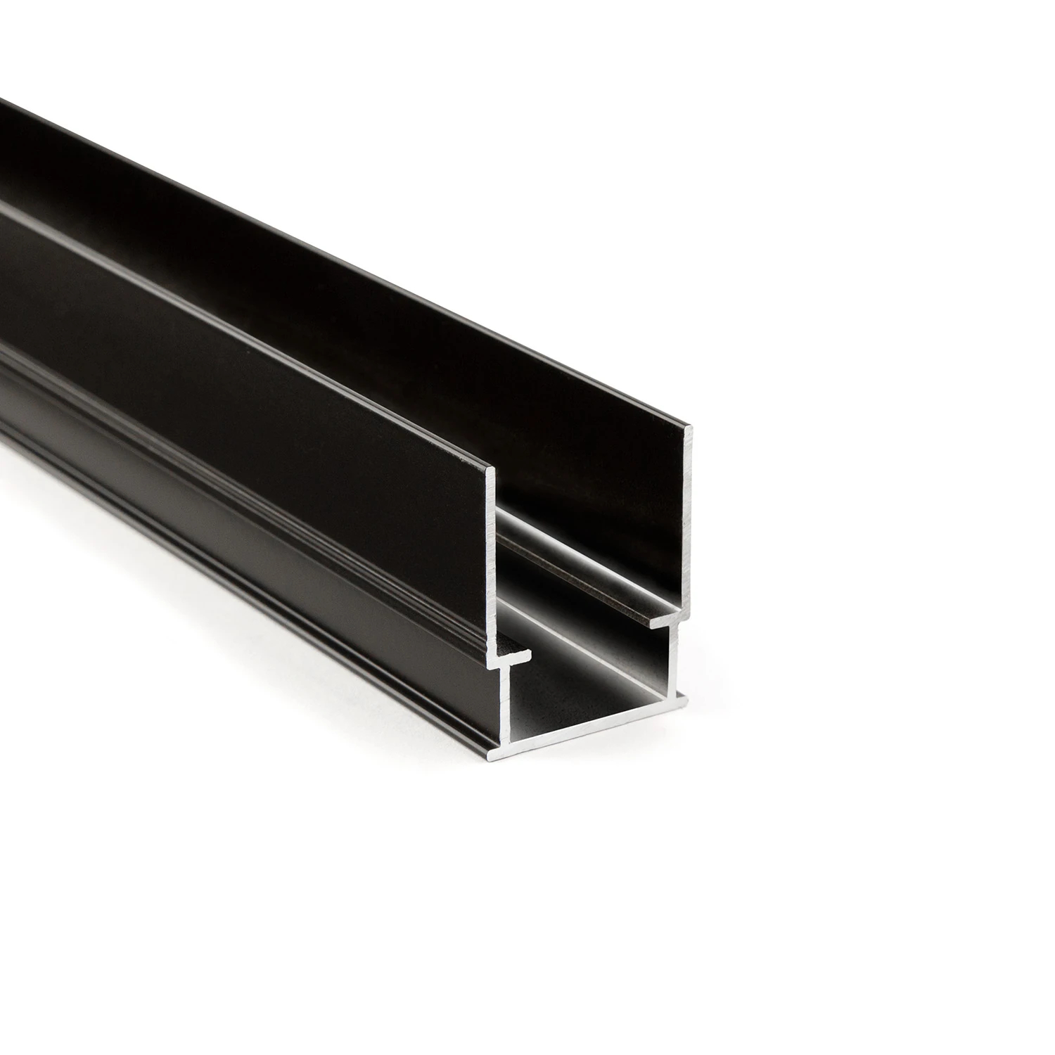
Concrete-embedded mounting profile
Prepare the light housing already in the in-situ concrete formwork
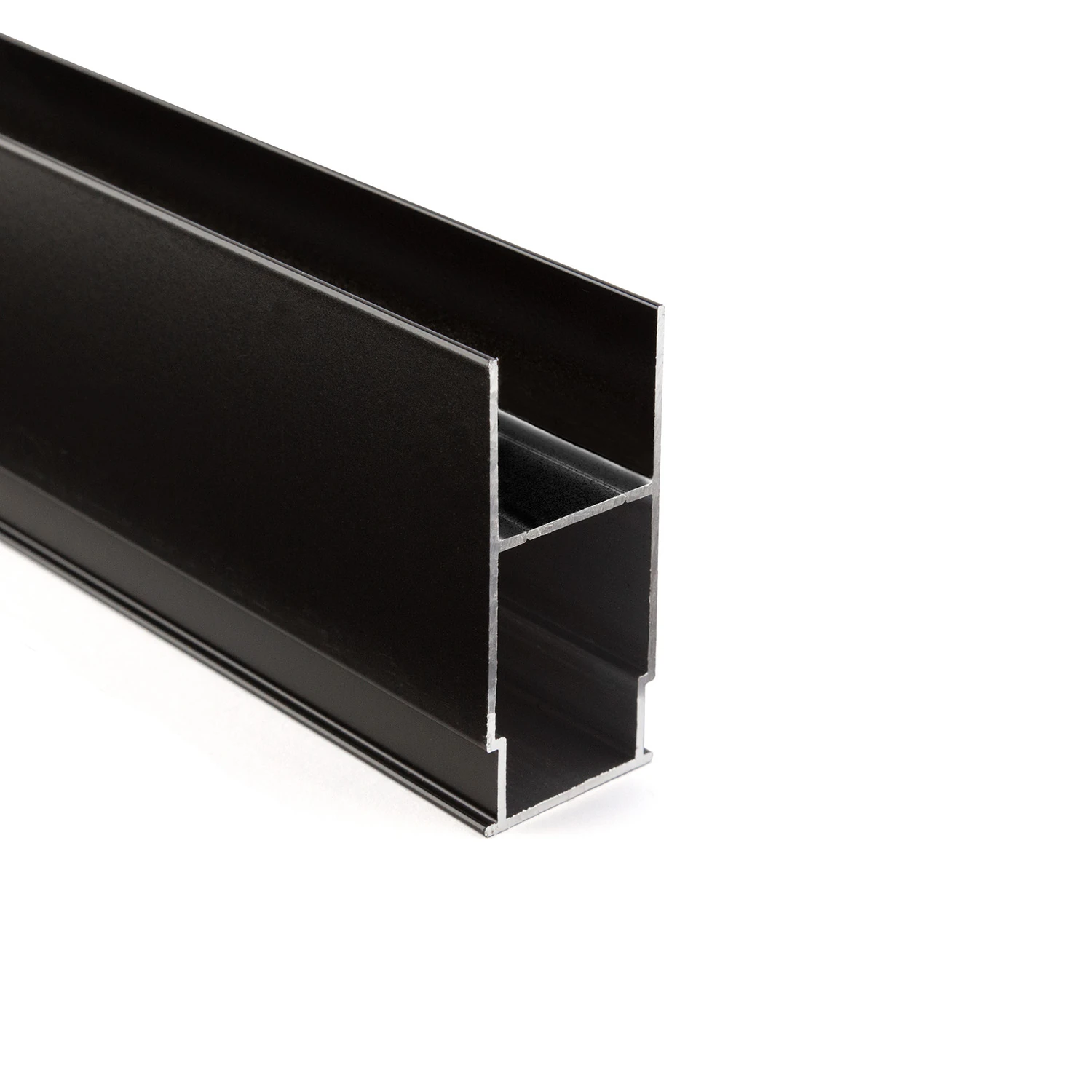
Concrete-embedded transformer profile
Supply technology accessible behind the luminaire insert
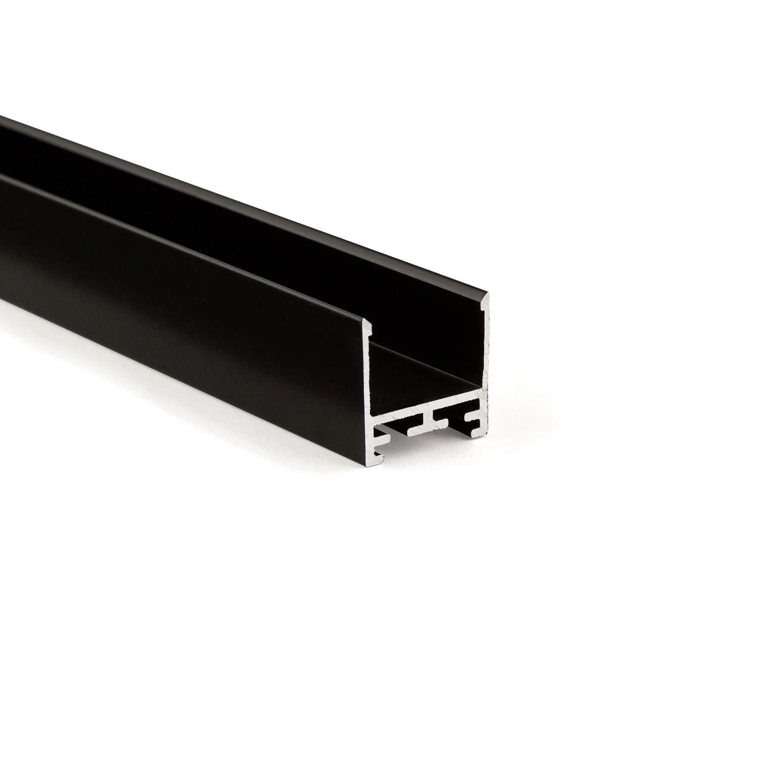
LL25 profile – the all-round visible profile
Consistent design language for recessed, surface-mounted and pendant installations
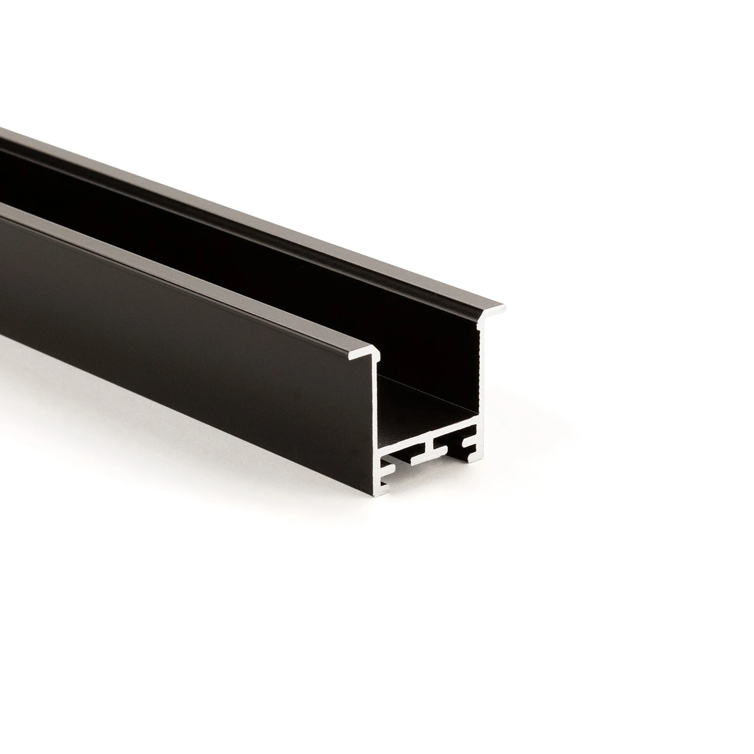
Recessed and visible profile LL35F
Visible aluminium edge covers the connection joint
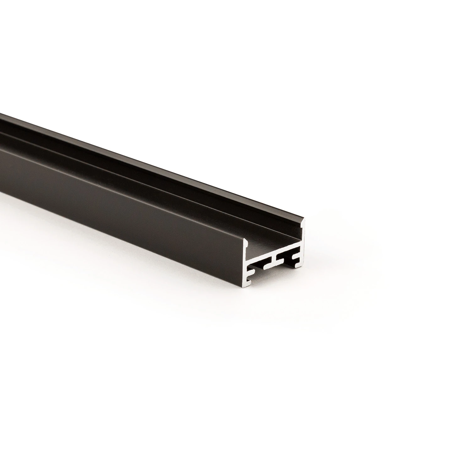
Visible profile LL2515
Compact aluminium body with sculptural V5 cover
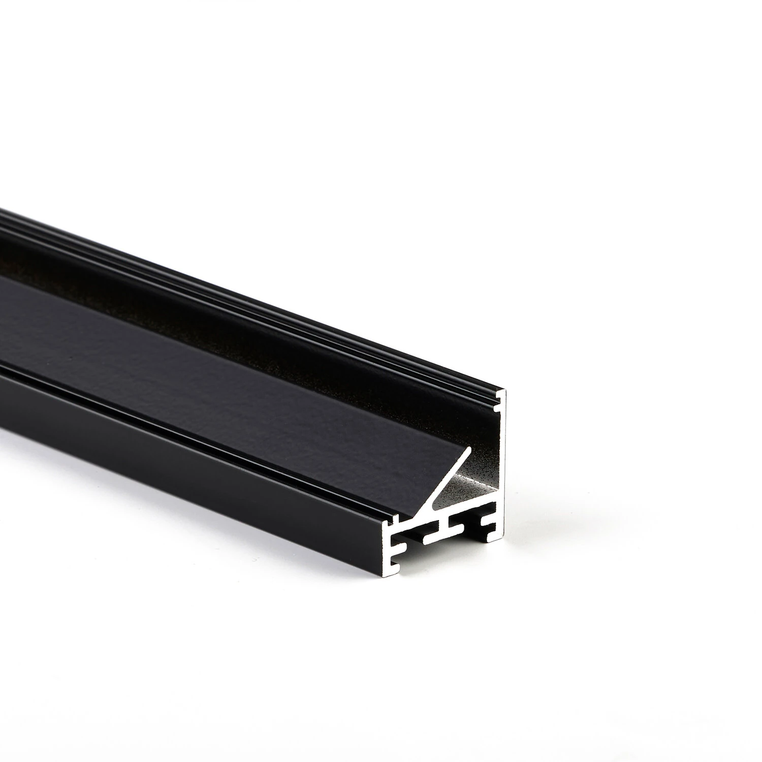
Corner visible profile LL2511E
45° inclined light-emitting surface for targeted aiming
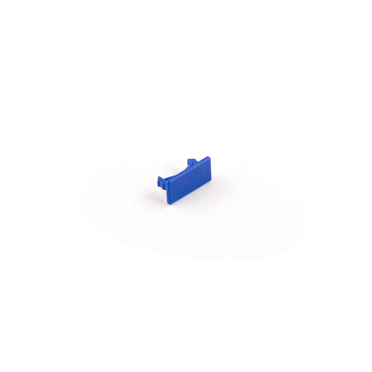
Mounting clips V1, V2 and V3
Height adjustment within the intended combination
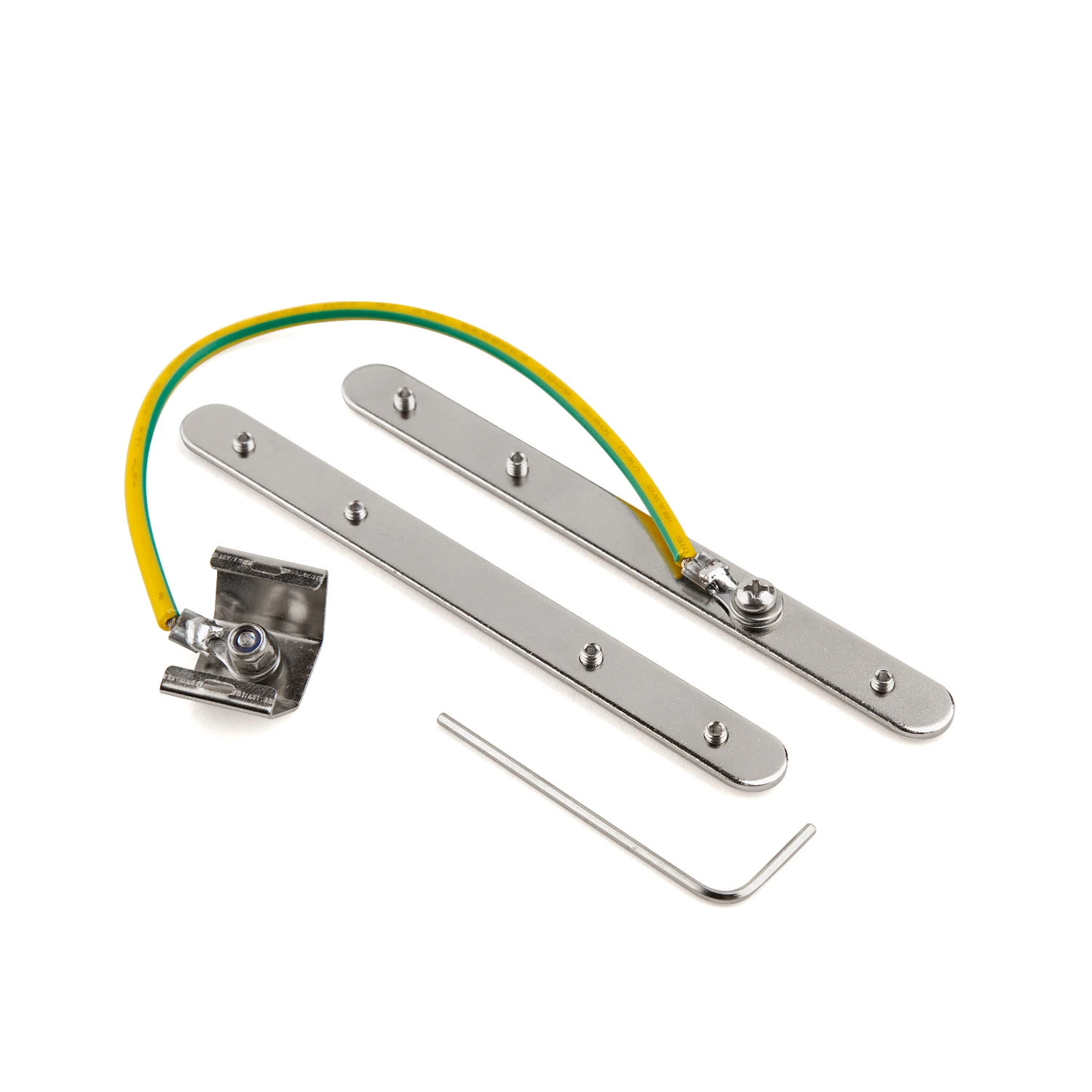
Fall protection for concrete installation
Connecting and securing at the profile joint
Light line found.
We'll clarify the details together.
Building material, surface and desired lighting effect set the direction. MPW supports you with the right system version and the next steps.
More possibilities for your architecture.
The solution. Experienced in the room.
Light lines in the finished room: the images show layout, integration and light effect. Open an image to enlarge the full shot.