

Suspended light lines
Slender light lines float in the room. As a pendant luminaire, LightLineLed brings light exactly where it is needed – above tables, work surfaces and open room zones.
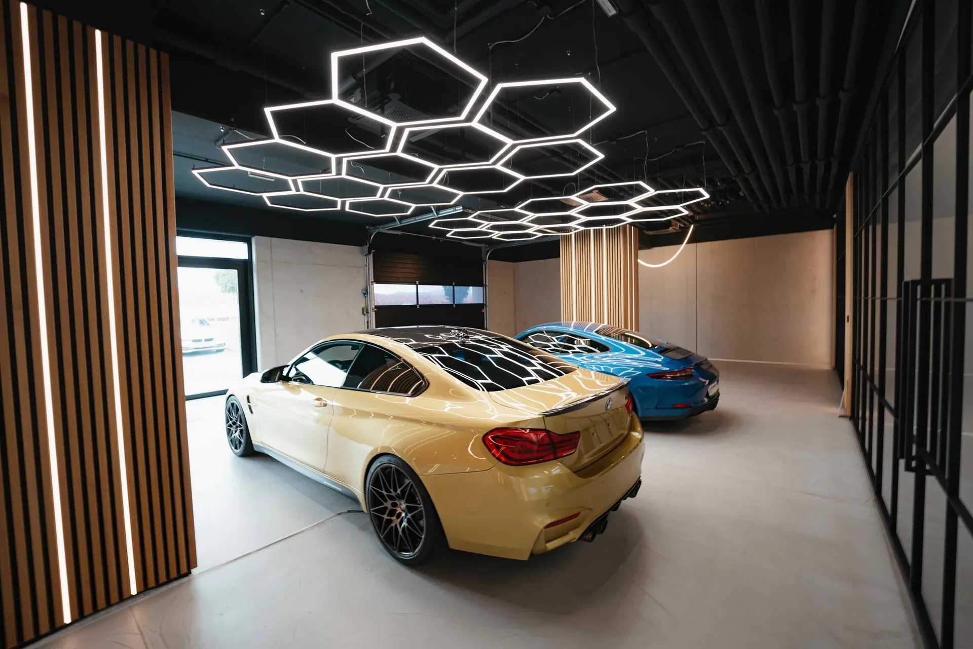
What this solution makes possible.
As a pendant luminaire, the light line becomes an independent part of the room. Three documented transformer arrangements create different technical and design possibilities. With a suitable variant, direct light can be supplemented by a separately controllable indirect component.
Slim visible profile with external supply.
Ceiling box as an accessible technical location.
Load-bearing surface-mounted transformer profile for integrated technology and optional indirect light.
This is how your line of light is made.
Application, construction and benefits – tailored to your architecture.
The line of light becomes a room object in its own right
As a suspended luminaire, LightLineLed detaches from the ceiling surface and sets a deliberately visible accent in the room. A linear pendant luminaire can accompany a table, structure a workstation or highlight an area within an open space. Height, length and profile shape are matched to the architecture. The suitable combination without lateral installation flanges creates a clean contour. In this way, the basic design idea of the line of light can also be used where the light is meant to work freely in the room.
Three ways to accommodate the power supply
With external power supply, only the slim visible profile is suspended. A separate ceiling box provides its own accessible technical location between the cable suspensions. Alternatively, a continuous surface-mounted transformer profile can be suspended together with the luminaire and house suitable control gear. These three variants differ in appearance, cable routing and technical compartment. The client can therefore decide, together with the planning, whether a particularly slender line, a separate technical area or a unified luminaire body is desired.
Complement direct light with room effect
With suitable versions, direct lighting can be combined with an additional indirect light component. A separate rear LED equipment with a matching cover can brighten the ceiling and complement the effect of the pendant luminaire in the room. This option exists for the documented variants with external supply or a load-bearing transformer profile. The ceiling-box variant shown emits direct light only. The desired lighting effect and the technical build-up are thus deliberately chosen together.
Linking design, prefabrication and installation
The luminaire can be prepared and tested as a coordinated unit before it is mounted at the planned cable points. Suspension, total weight and cable routing depend on the specific geometry. Suitable technical areas and planned access support later service. The sections show how ceiling connection, cable guide and profile combination belong together. This turns the desired pendant form into a comprehensible system solution whose visible design and technical preparation are matched to each other.
The solution in section
The system as construction progresses.
From the prepared housing to the finished light line.
The path to the finished light line
Coordinate shape and power supply
Determine total weight including transformer, ceiling substrate, height and lighting effect. Match power supply, cable and LED system to one another.
Set the suspension points
Determine cable positions and number according to load and geometry. The NewLux cover plate for 68 mm flush-mounted boxes with cable guide and strain relief is recommended as a ceiling outlet in the installation manual.
Connect and secure profiles
With a load-bearing surface-mounted transformer profile, secure the visible-profile insert separately. The surface-mounted connectors engage both rear slots; attach the free eyelet to the load-bearing profile.
Complete the lighting technology
Offset clips and cables lengthwise. For variant 1/3, optionally run a second LED strip with V4-HL-25 along the length and leave it out only at the cable hangers. Finally check hold and function.
Installation & documents.
The installation and processing instructions accompany the actual implementation of your line of light.
Suspended lines of light · Installation & processing
PDF · matching instructions
Safety and installation notes
PDF · observe together with the instructions
The complete installation manual
All applications and system details
Processing notes in detailMounting clips, safety cable and further notes on the specific design
Build-up details
Variant 1: Only the visible profile is suspended; the driver is external. The DC cable runs from the ceiling outlet to the support cable and along the cable to the profile.
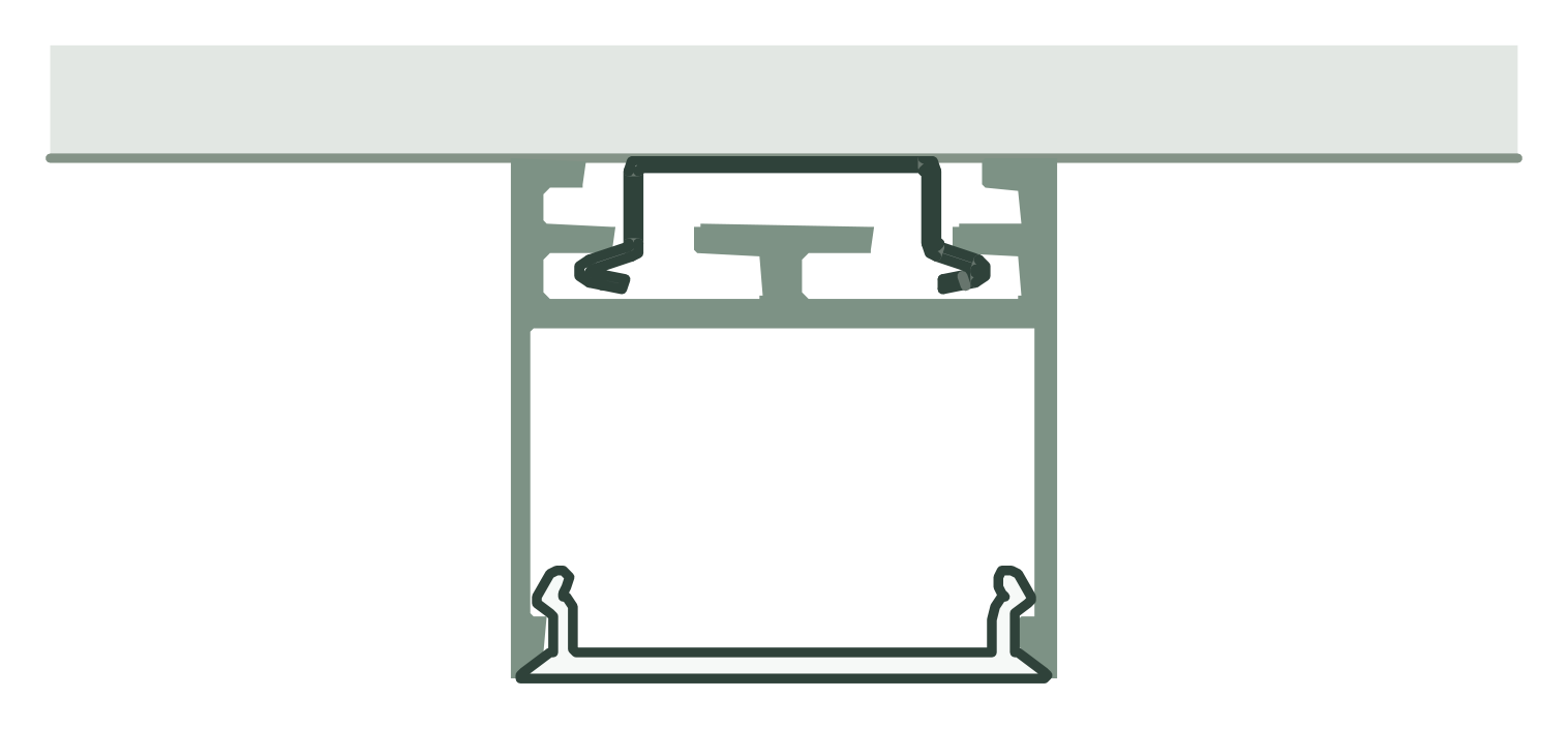
Variant 2: surface-mounted transformer box with LL2509 lid sits on the ceiling between the cable suspensions. The version shown emits direct light only.
Variant 3: The continuous surface-mounted transformer profile is suspended as well and carries the visible profile via V1 clips. The 230 V supply line is routed protected and separately strain-relieved along the cable.
Processing and installation
At least one suspension cable per metre started, and at least two suspension points per unit. The example of 3 m with 1 m cable spacing and end points gives four points; the actual load calculation remains decisive.
The support cable carries the luminaire; the supply cable needs its own strain relief. For separate switching, provide two controllable lighting circuits.
Transformer in the build-up shown: maximum 18 mm high. Additionally restrain the LL2509 lid mechanically.
For surface-mounted and suspended installations, use only visible profiles and covers without side aluminium or PMMA cover flanges. Suitable combinations are LL2515 + V5-U-2510, LL25 + V1-AP-25, LL25 + V5-U-2510 and LL2511E + V6-E-2511.
Before cutting, measure the temperature of the profile and cover. Allow room for movement at joints and end caps for heating and cooling, and clip in the cover free of stress.
Discover the matching products.
Profiles, covers and accessories together make up your light line. The product pages show versions and matching combinations.
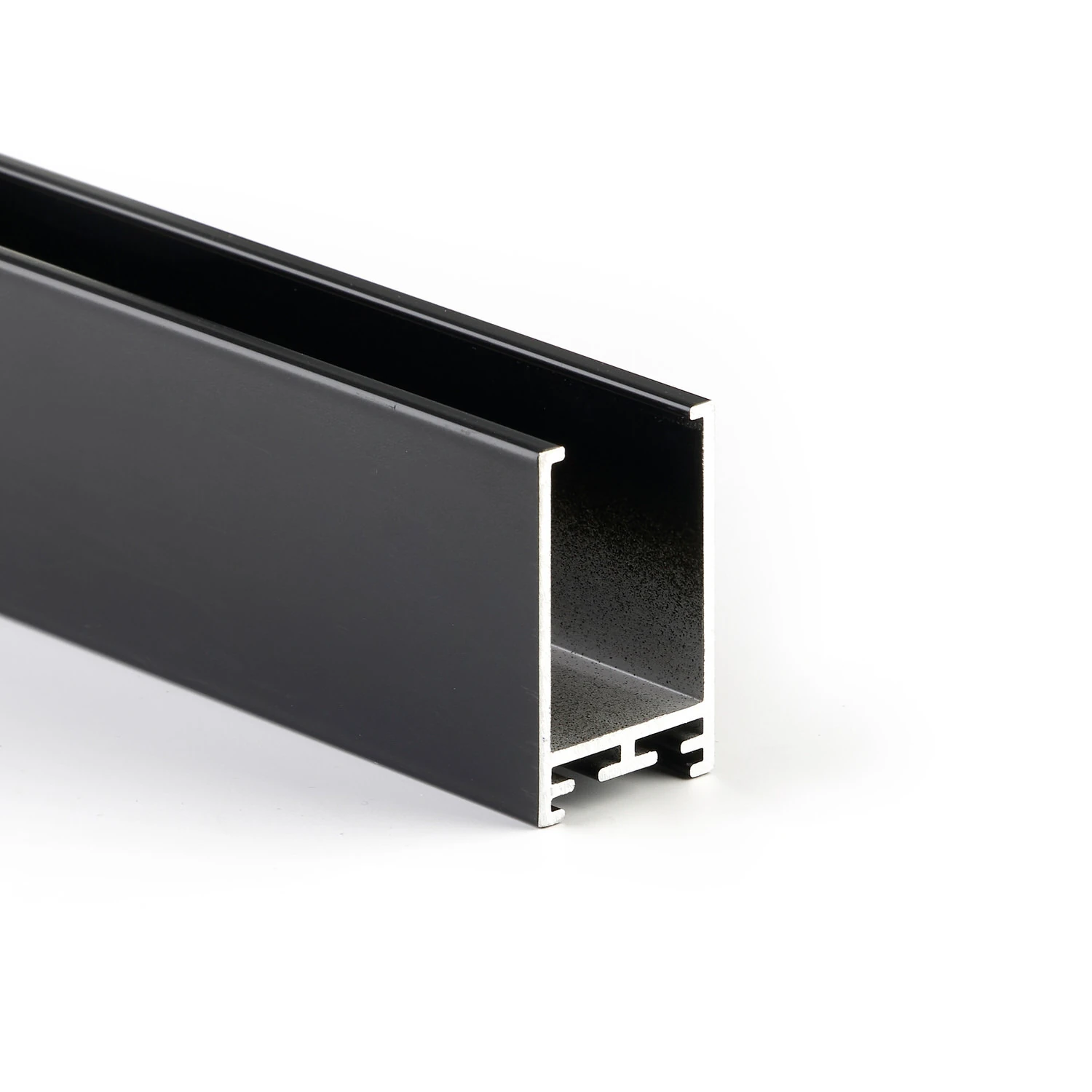
Surface-mount driver profile
Power supply technology in the formal language of the luminaire
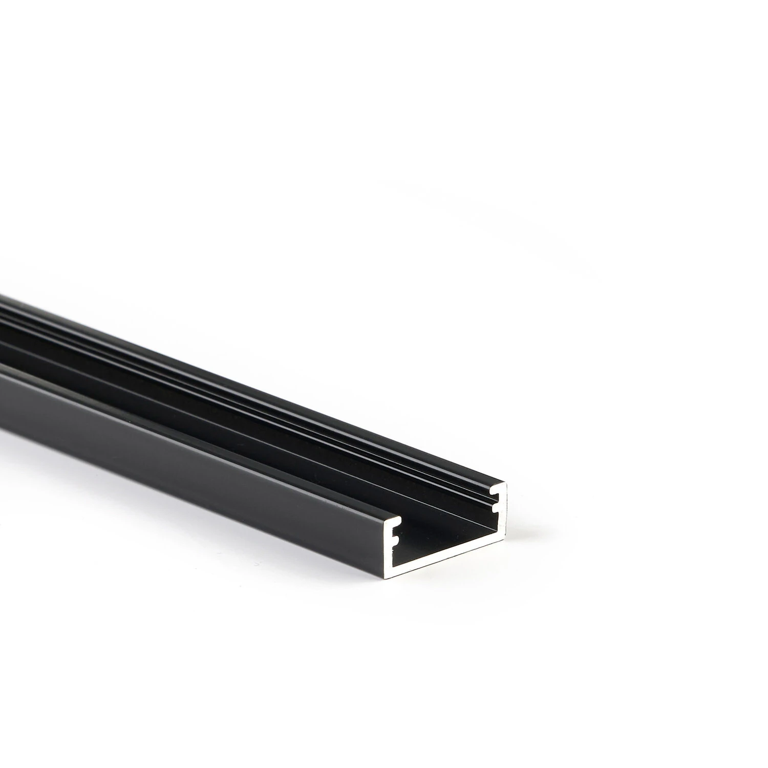
Multi-profile LL2509
Four tasks within the same system family
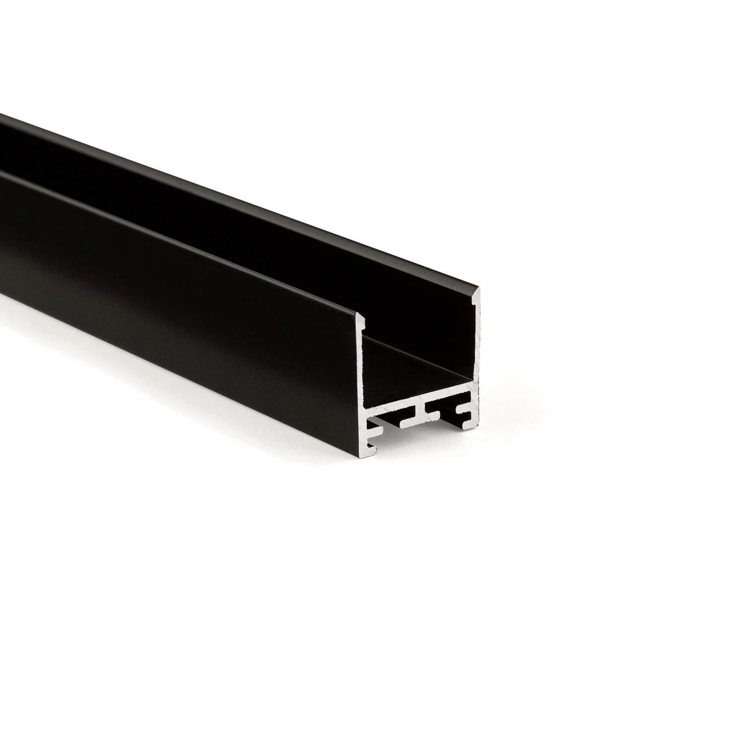
LL25 profile – the all-round visible profile
Consistent design language for recessed, surface-mounted and pendant installations
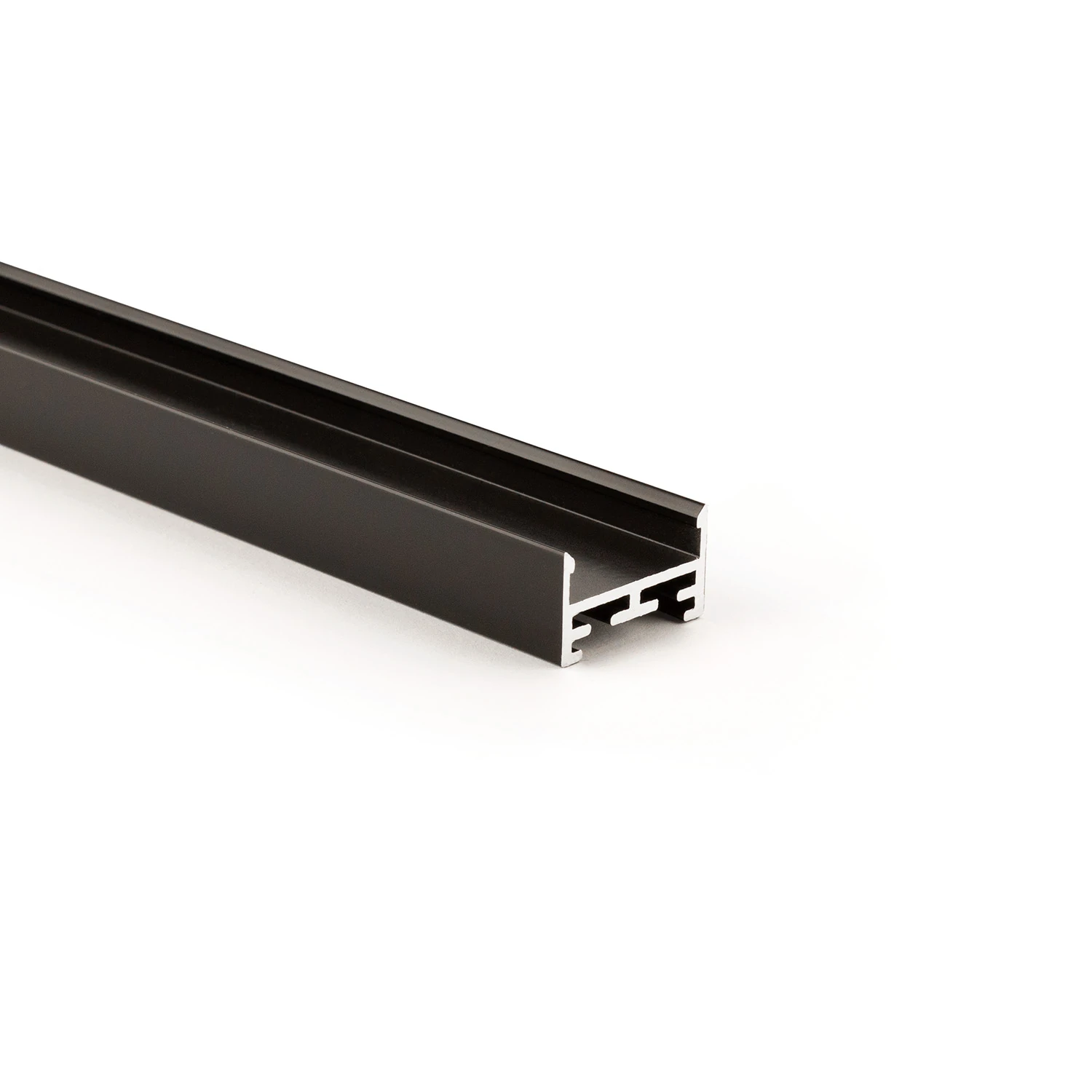
Visible profile LL2515
Compact aluminium body with sculptural V5 cover
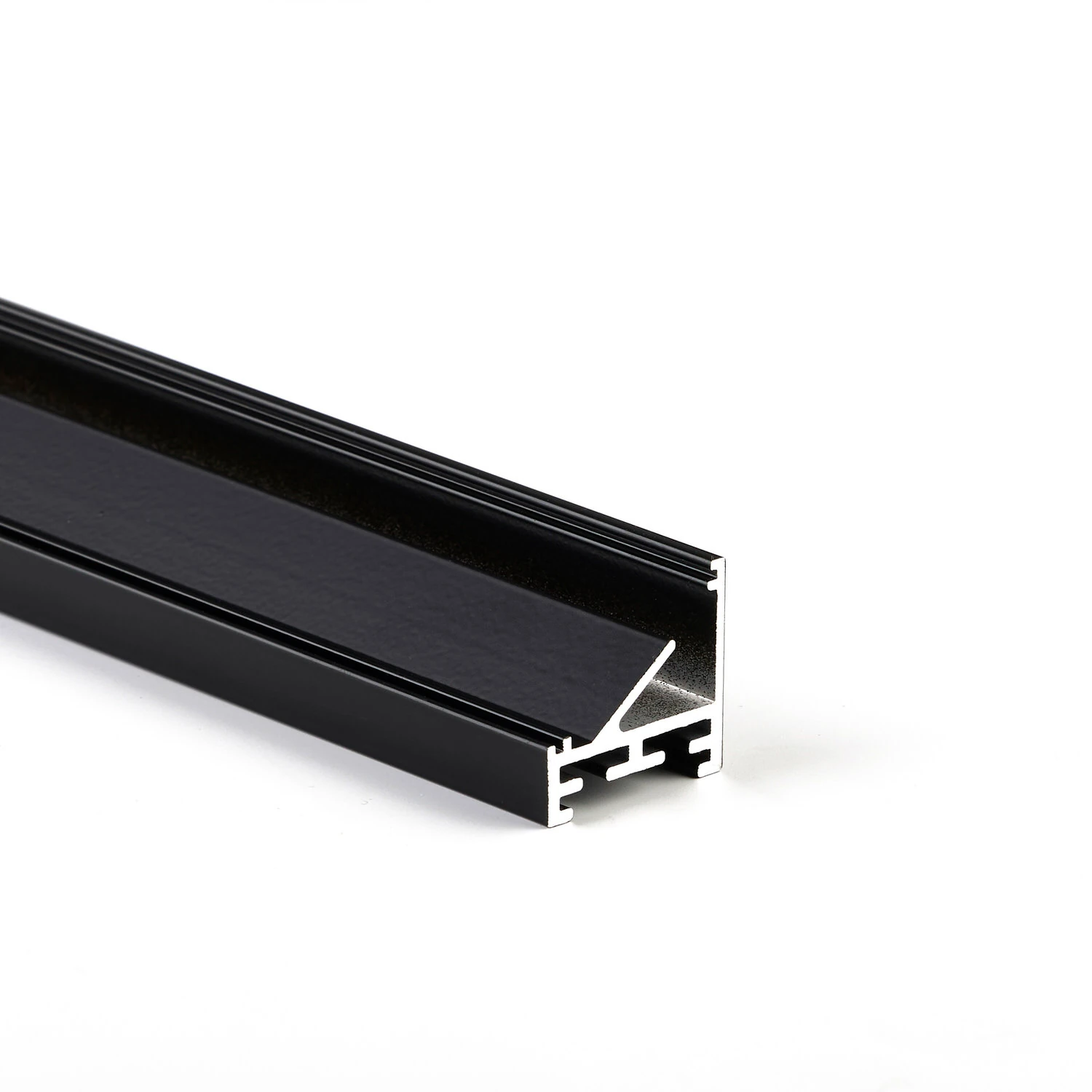
Corner visible profile LL2511E
45° inclined light-emitting surface for targeted aiming
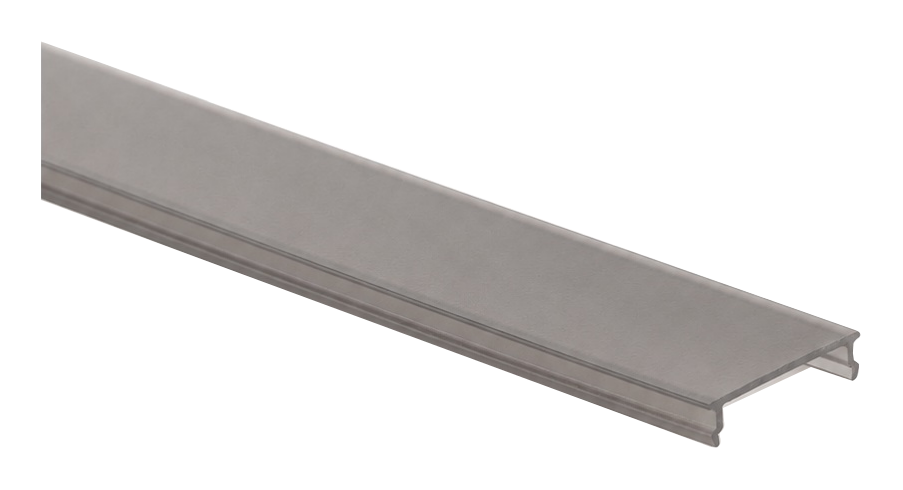
V4-HL-25 cover
Defined visible termination
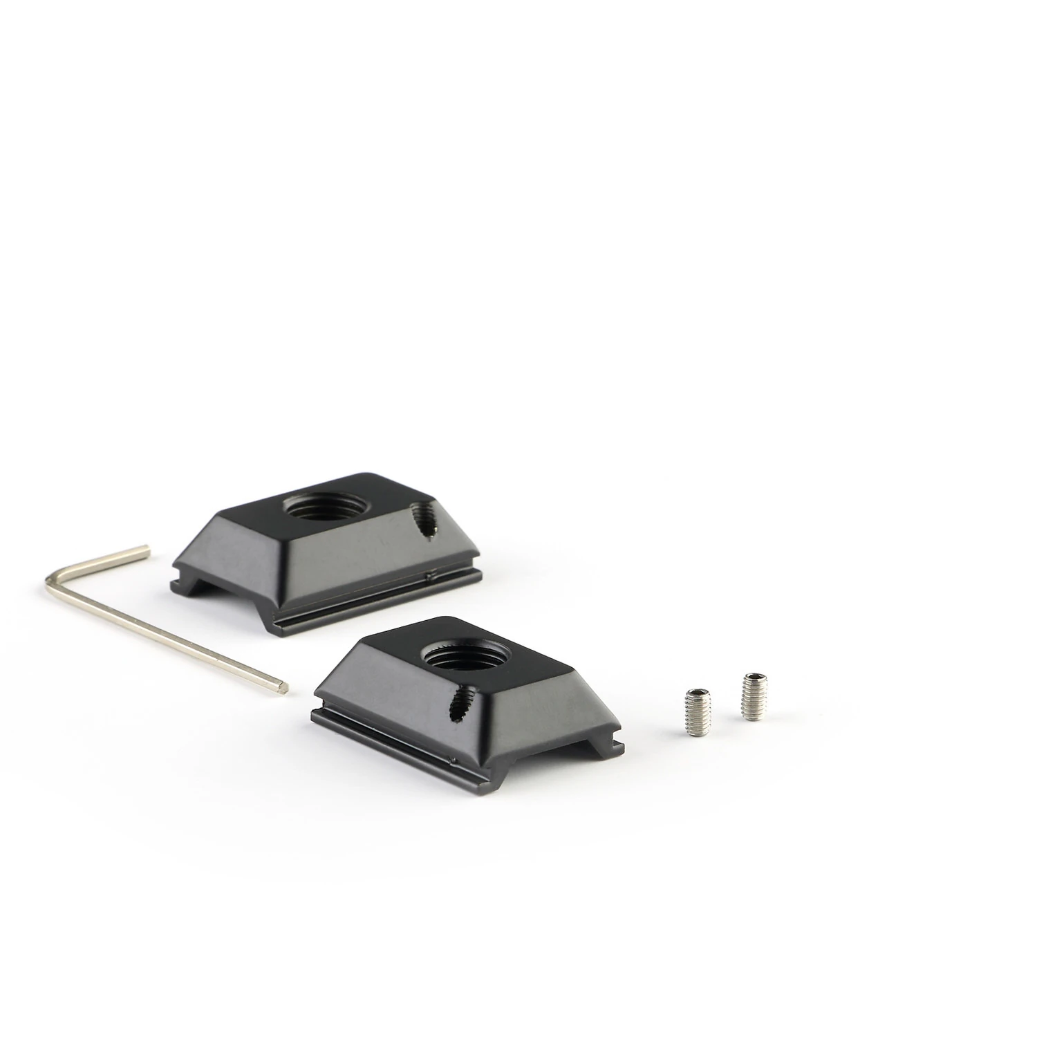
Cable suspension with T-nut
Pendant lighting with clear lines
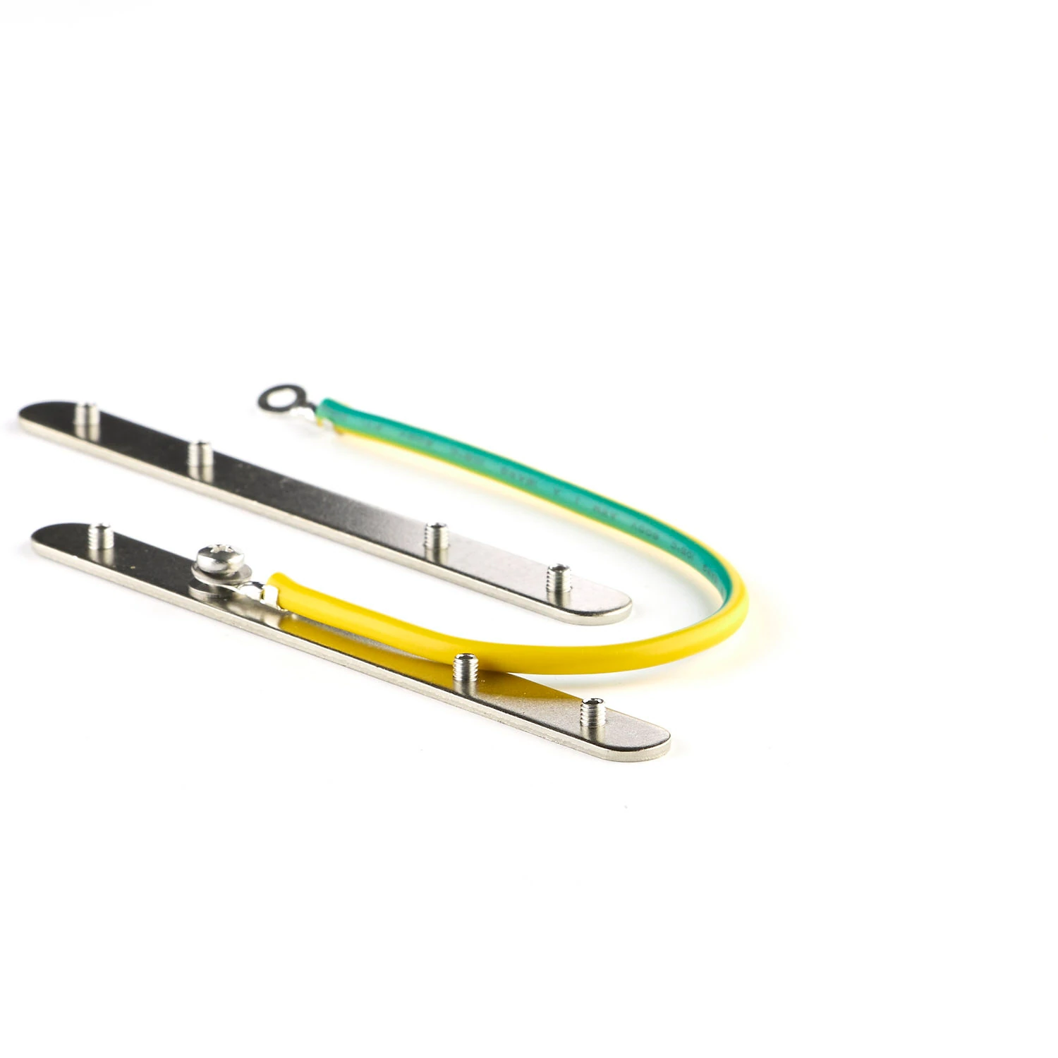
Fall protection for surface-mounted and pendant use
Connecting and securing at the profile joint
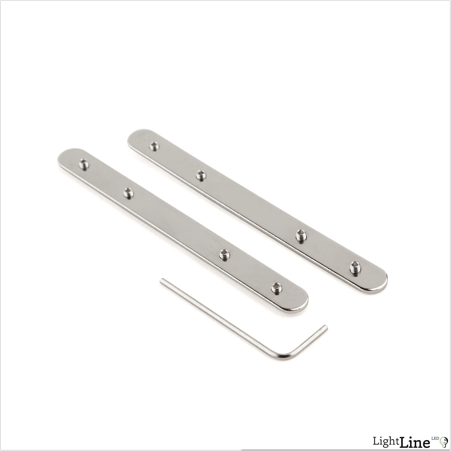
Profile connectors for lines and angles
Straight and three-dimensional profile transitions
Light line found.
We'll clarify the details together.
Building material, surface and desired lighting effect set the direction. MPW supports you with the right system version and the next steps.
More possibilities for your architecture.
 14
Surface mounting
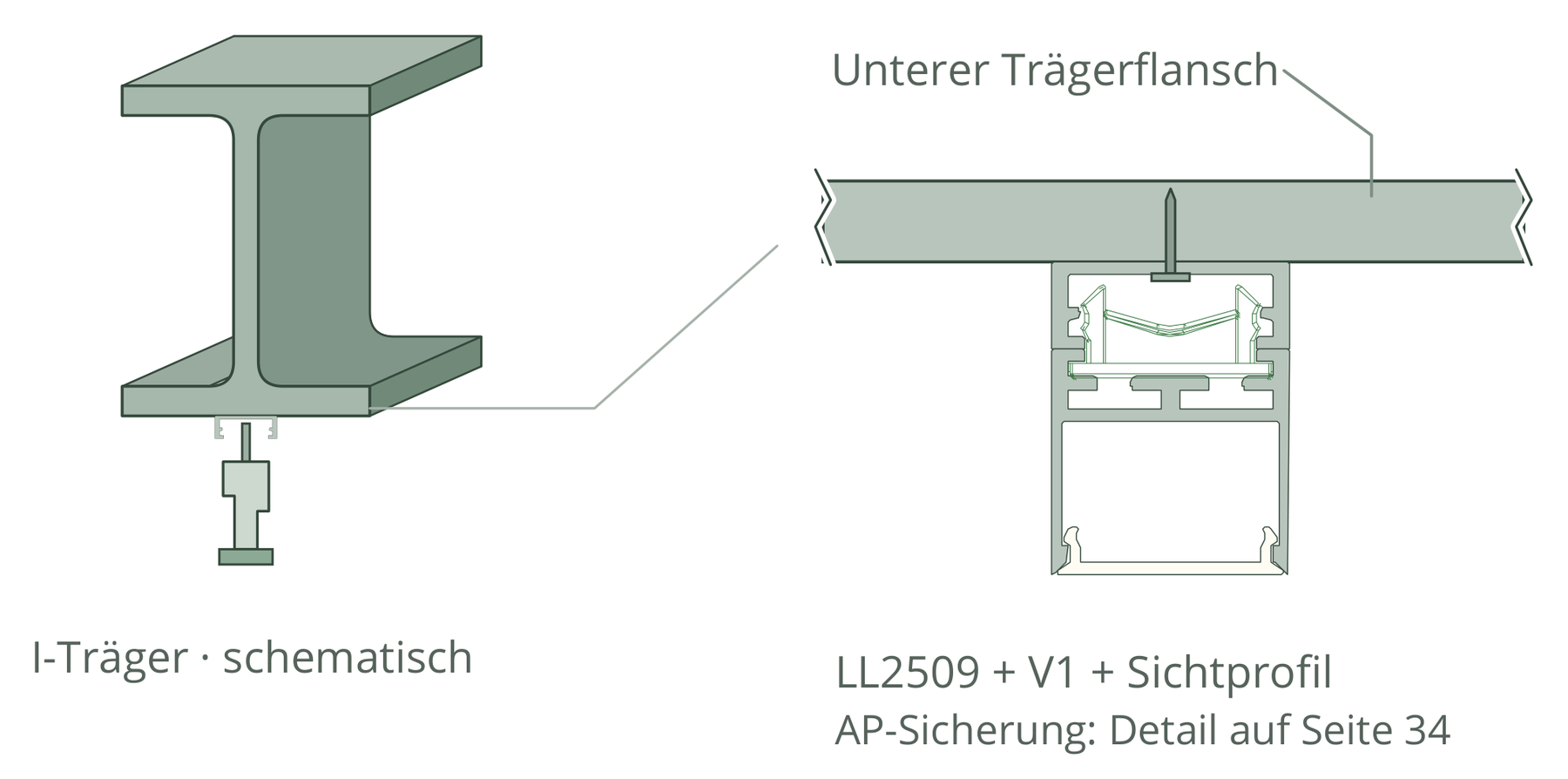
Surface-mounted with metal clip, cavity spring or LL2509 as mounting base.
 15
LL2509 as a multi-profile
Mounting base, mini light profile or blind cover: one component, several tasks.
 17
Shaped-part & magnetic mounting
Wall brackets and magnetic base plates for special mounting tasks.
The solution. Experienced in the room.
Light lines in the finished room: the images show layout, integration and light effect. Open an image to enlarge the full shot.