

Surface mounting
A clear light line directly on the ceiling or component. LightLineLed creates visible, slender luminaires for rooms where a surface-mounted solution suits the architecture.
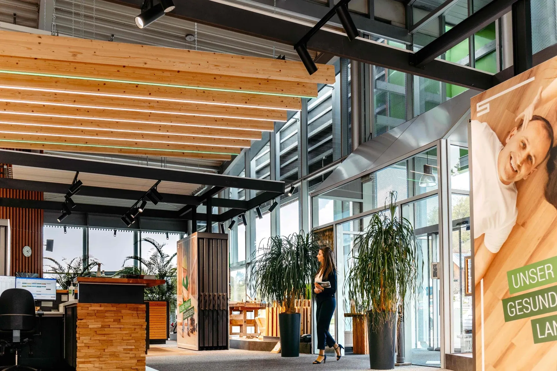
What this solution makes possible.
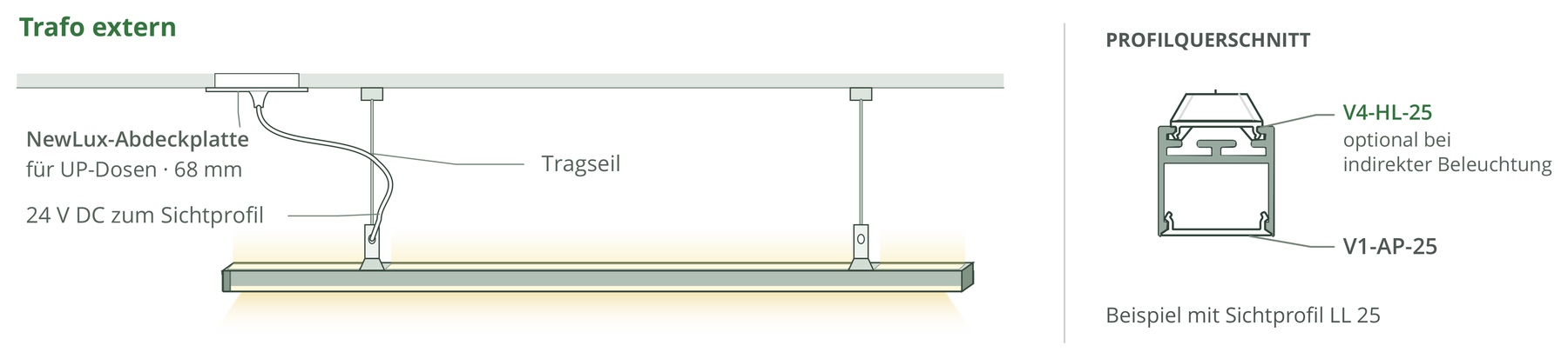
A clean line of light doesn't necessarily need a recessed channel. With metal clips, cavity springs or the LL2509 mounting profile, it can be fixed to suitable ceilings and building elements. Power supply and electronics can be placed externally, in a ceiling box or in the continuous surface-mounted driver profile.
Three installation types to suit substrate and build-up.
Prefabrication of the light insert and a clear installation sequence.
Uniform line layout even with a separate technical housing.
This is how your line of light is made.
Application, construction and benefits – tailored to your architecture.
A clear light line on the existing surface
LightLineLed can also be mounted visibly on walls and ceilings. This is an interesting solution when the surface is to remain or a slim luminaire body is deliberately desired. The line can accompany room axes and continue the same design idea used elsewhere in the building as a recessed luminaire. For surface mounting, suitable visible profiles and covers without lateral installation wings are chosen. Their cross-section and light outlet determine the visible character of the luminaire.
Choose the fastening to suit the substrate
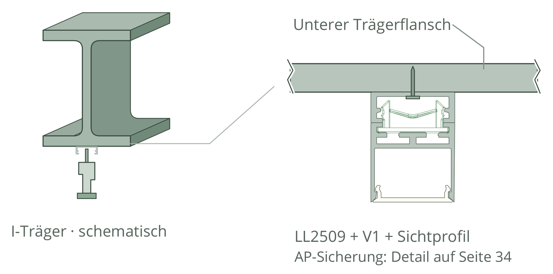
Metal clips, suitable cavity springs or LL2509 as a mounting base open up different fixing routes. The choice depends on the substrate, load and desired build-up. LL2509 can create a separate mounting plane that receives a compatible visible profile. This allows the fixing to be prepared before the fitted luminaire insert follows. The sections show the differences and make clear which system parts belong together for each situation.
Include the supply in the design
The electronics can be located outside the luminaire, in a separate ceiling box or in a suitable surface-mounted driver profile. External supply allows a particularly slim visible build-up. An integrated technical area, by contrast, creates a coherent luminaire body with space for suitable control gear and connections. Which variant fits depends on cable route, device dimensions and the desired spatial effect. This allows the technical location and appearance to be chosen together, rather than fixing the supply only after the profile has been selected.
Use prefabrication and later access
Visible profile, LED strip and cover can be prepared and tested as a light unit. On site, fixing suited to the substrate, connection and the intended securing follow. With a planned removal path, the suitable insert remains accessible later. LL2509 serves as the mounting base where applicable; the matching fall protection secures the compatible visible profile. For the client, the result is a comprehensible combination of visible form, suitable mounting method and lighting technology whose maintenance has already been considered.
The solution in section
The system as construction progresses.
From the prepared housing to the finished light line.
The path to the finished light line
Define installation and power supply
Check the substrate, total weight, cable route and accessible driver location. Match fasteners to the specific application.
Mount the load-bearing layer
Align and fix metal clips, LL2509 or driver profile. Route cables protected and do not trap them between clip and profile.
Connect and secure the insert
Slide matching connectors into both rear slots of the visible profile. Connect both sections at the joint; secure the start, every joint and the end with the surface-mount fall-protection device.
Latch in and check
Hook the visible profile in from the side and swivel it in, or clip it in with V1. Check full seating, ring eyelet fastening, cables and function.
Installation & documents.
The installation and processing instructions accompany the actual implementation of your line of light.
Surface mounting · Installation & processing
PDF · matching instructions
Safety and installation notes
PDF · observe together with the instructions
The complete installation manual
All applications and system details
Processing notes in detailMounting clips, safety cable and further notes on the specific design
Build-up details
Surface-mount metal clip: screw to a level, load-bearing substrate; position the visible profile from the side and swivel it in.
AP cavity spring: mount on the profile and let it spread out behind a suitable load-bearing board.
LL2509: fix to the load-bearing component; insert a compatible visible profile with V1 clips, 10 mm.
Processing and installation
AP metal clips: one per 0.5 m (rounded up) plus one additional; for 1/2/3 m that makes 3/5/7 pieces. AP cavity springs and V1 in LL2509: four per metre, at least two per section.
A plugged-in continuous surface-mounted transformer profile and visible profile must be secured on both levels. With a through-screwed housing, the screws provide its fastening.
Screw the AP eyelet to the load-bearing component or load-bearing profile. LL2509 covers have no securing grooves and need separate mechanical retention.
For surface-mounted and suspended installations, use only visible profiles and covers without side aluminium or PMMA cover flanges. Suitable combinations are LL2515 + V5-U-2510, LL25 + V1-AP-25, LL25 + V5-U-2510 and LL2511E + V6-E-2511.
Before cutting, measure the temperature of the profile and cover. Allow room for movement at joints and end caps for heating and cooling, and clip in the cover free of stress.
Discover the matching products.
Profiles, covers and accessories together make up your light line. The product pages show versions and matching combinations.
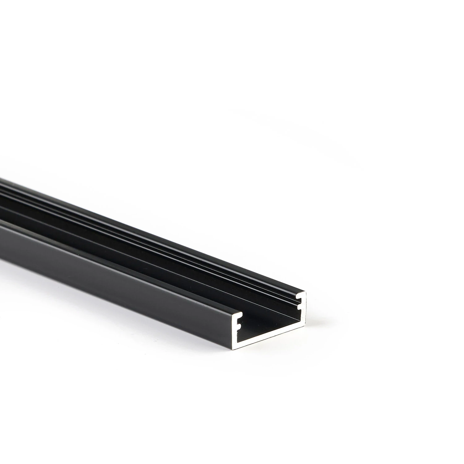
Multi-profile LL2509
Four tasks within the same system family
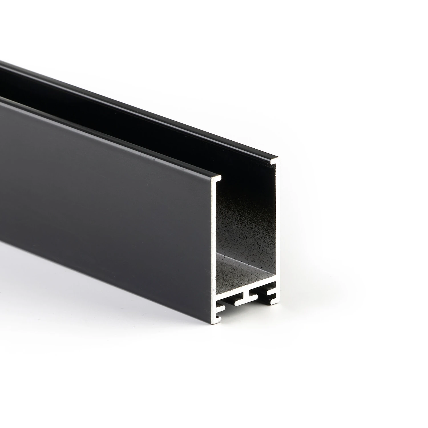
Surface-mount driver profile
Power supply technology in the formal language of the luminaire
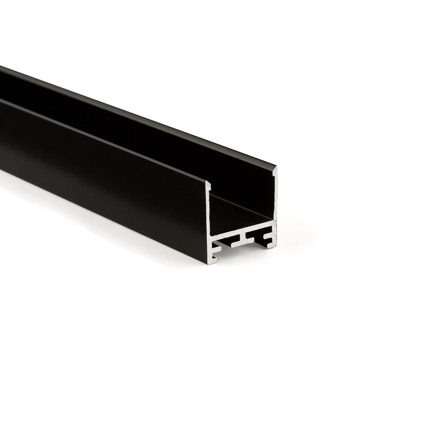
LL25 profile – the all-round visible profile
Consistent design language for recessed, surface-mounted and pendant installations
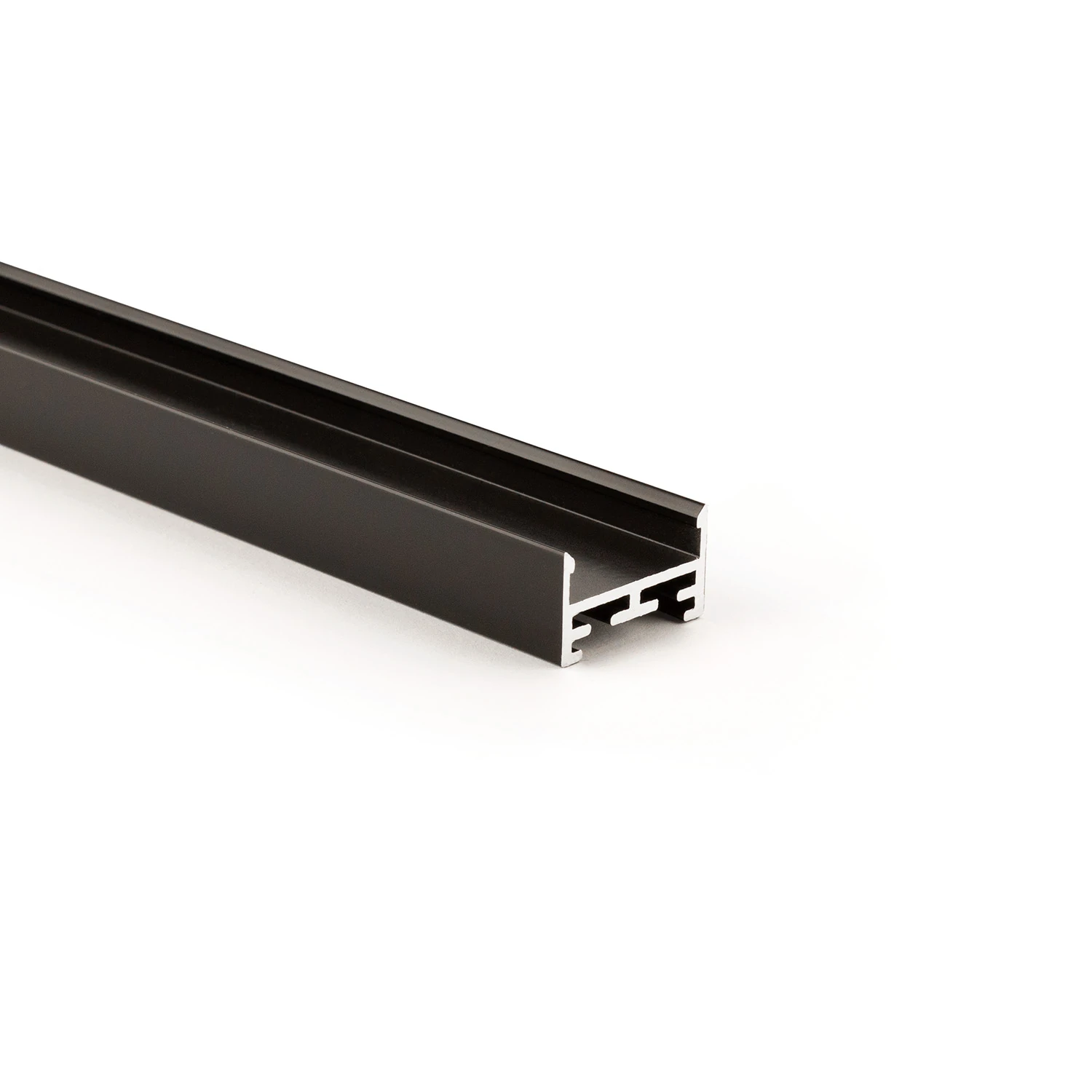
Visible profile LL2515
Compact aluminium body with sculptural V5 cover
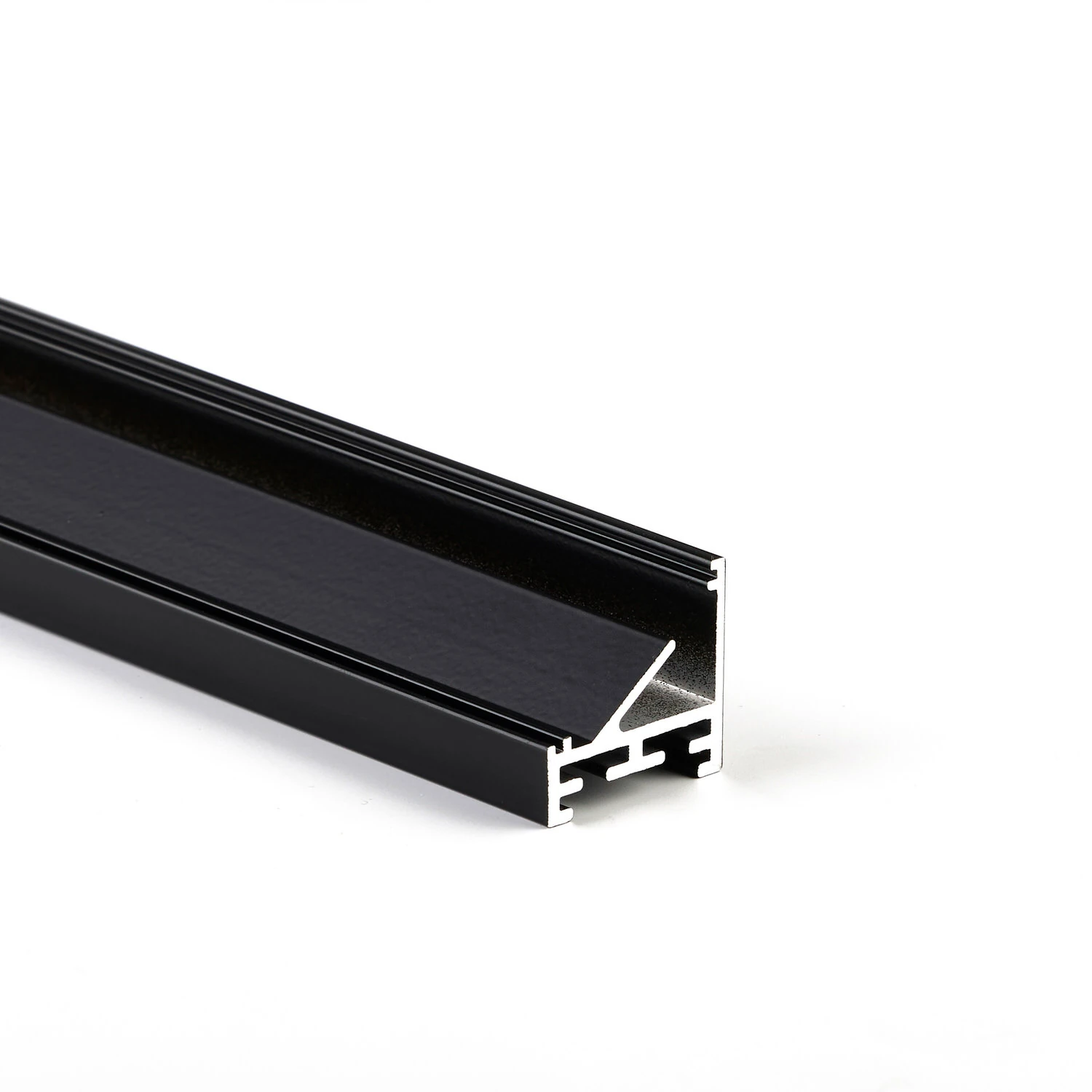
Corner visible profile LL2511E
45° inclined light-emitting surface for targeted aiming
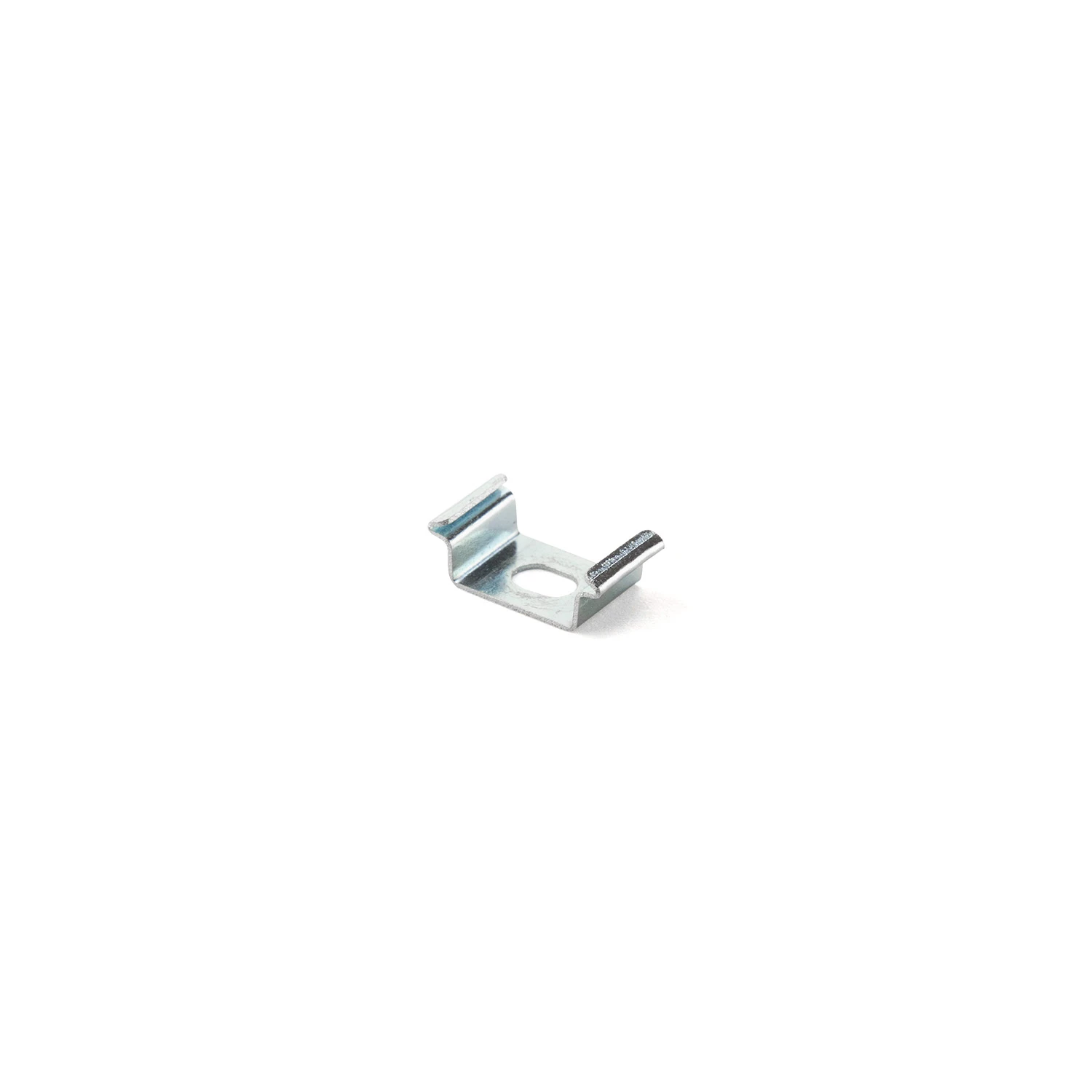
Metal clips and mounting springs
Direct mounting without a continuous flush-mount profile
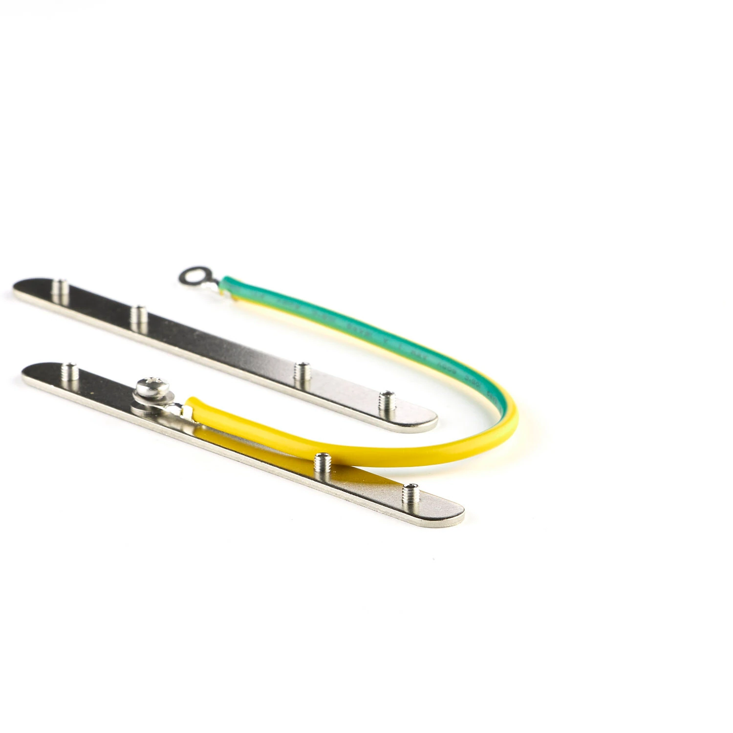
Fall protection for surface-mounted and pendant use
Connecting and securing at the profile joint
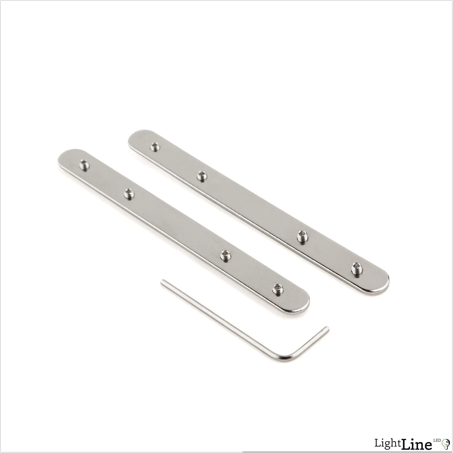
Profile connectors for lines and angles
Straight and three-dimensional profile transitions
Light line found.
We'll clarify the details together.
Building material, surface and desired lighting effect set the direction. MPW supports you with the right system version and the next steps.
More possibilities for your architecture.
 15
LL2509 as a multi-profile
Mounting base, mini light profile or blind cover: one component, several tasks.
 16
Suspended light lines
Slender pendant luminaires with external, separate or integrated technology.
 17
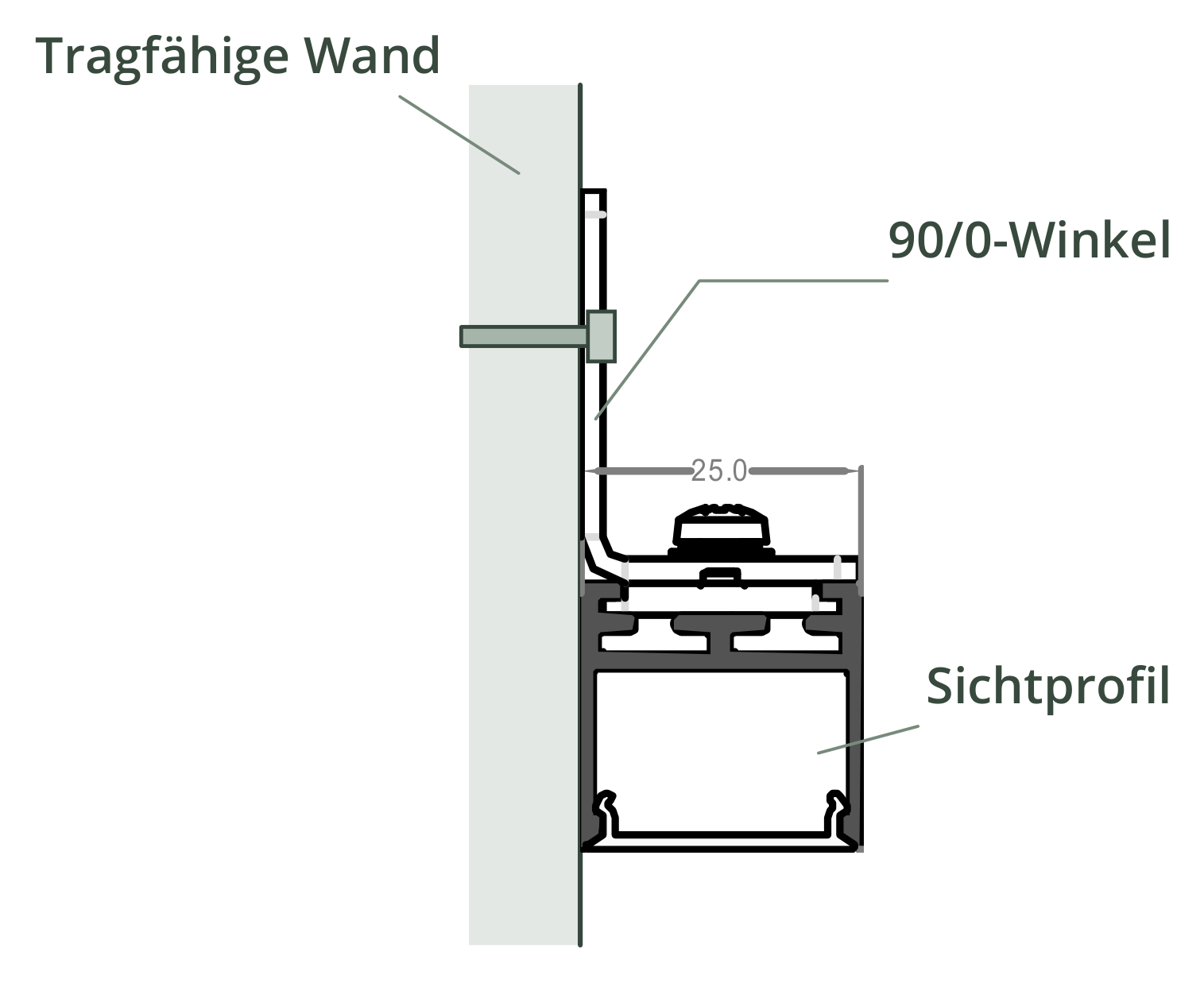
Shaped-part & magnetic mounting
Wall brackets and magnetic base plates for special mounting tasks.
The solution. Experienced in the room.
Light lines in the finished room: the images show layout, integration and light effect. Open an image to enlarge the full shot.