

Shaped-part & magnetic mounting
New fastening routes open up new lighting ideas. Brackets, base plates and magnet sets make LightLineLed usable for wall, spaced and removable installations.
What this solution makes possible.
Wall, spacer mounting or removable fastening to steel: a mounting base plate opens up various connections for suitable visible profiles. Stainless steel molded parts and magnets are chosen according to the component and the desired light direction.
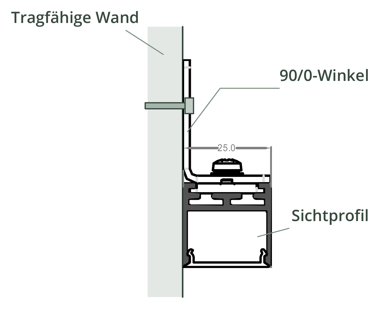
Lateral wall mounting with 90/0 bracket.
Distance from the component via U-bracket or flat connection with 0/0 sheet.
Removable magnetic mounting with independent mechanical securing.
This is how your line of light is made.
Application, construction and benefits – tailored to your architecture.
Adapt light lines to special installation situations
Not every light line sits directly on a flat ceiling. LightLineLed therefore complements the usual recessed and surface-mounted variants with matching shaped parts and its own magnetic mounting. This allows suitable visible profiles to be fixed to the side of a wall, at a distance from a component, or removably to suitable steel. The desired light direction and the existing substrate set the direction. The line design can thus be continued even at unusual mounting locations, without separating the fixing task from the luminaire design.
One base plate for different connections
The mounting base plate is fixed in the rear channel of the suitable visible profile and forms the connection for the chosen shaped part. Brackets allow lateral fixings, U-shaped parts create spacing and flat plates provide a corresponding connection to the building element. The choice depends on the profile, orientation and load. The drawings make these differences visible. For planning, this creates a concrete link between the desired light output and the mechanical connection to the existing structure.
Magnetic mounting for suitable steel surfaces
In the magnetic version, the prepared luminaire is held on a suitable ferromagnetic steel surface. This can be of interest where a removable unit is desired and the actual counter-surface provides the necessary holding force. Magnet and independent mechanical securing perform different tasks and are therefore connected separately. The holding force is tested on the actual component. The advantage is a deliberately detachable mounting connection whose suitability is matched to surface, load and installation position.
Prepare the light unit properly
Visible profile, cover and LED fitting are selected together with the fixing method. For visibly surface-mounted lines of light, suitable combinations without lateral installation flanges are used. The unit can be prepared and tested before it is fixed at the planned installation location. When it is later removed, it is supported and released in a controlled manner. The shaped-part and magnetic variants thus combine the design possibilities of LightLineLed with a clearly described installation task matched to the respective substrate.
The solution in section
The system as construction progresses.
From the prepared housing to the finished light line.
The path to the finished light line
Choose the fixing principle
Check substrate, profile, shaped part and alignment together. A screwed angle component does not need a metallic substrate; the magnet, however, needs suitable ferromagnetic steel.
Fix the base plate in the profile
Position the mounting plate and tighten all four M3 clamping screws. Fix the matching fitting or magnet with the intended M4 screws.
Mount on a load-bearing component
Attach the bracket or mounting plate with suitable fasteners. Provide at least two fixing points per line of light; further points according to load and installation position.
Secure the magnetic unit separately
For magnetic mounting, use an independent load-bearing securing point. Test the holding force on the actual component and secure every removable unit. When removing, support the luminaire and release it in a controlled manner.
Installation & documents.
The installation and processing instructions accompany the actual implementation of your line of light.
Shaped-part & magnetic mounting · Installation & processing
PDF · matching instructions
Safety and installation notes
PDF · observe together with the instructions
The complete installation manual
All applications and system details
Processing notes in detailMounting clips, safety cable and further notes on the specific design
Build-up details
The mounting base plate sits in the groove at the back of the profile and is fixed with four M3 clamping screws.
The stainless steel shaped part is fixed with the intended M4 screws. Screws must not protrude at the bottom; with the 0/0 plate, countersunk heads sit flush.
With magnet mounting, the magnet sits on one M4 thread and the safety cable on the second. The free end of the safety cable is attached independently of the magnet.
Processing and installation
Paint, rust, air gaps and thin sheet metal reduce magnetic holding force. A nominal holding force is not a permissible overhead load.
The fall-protection device must not come loose together with the magnet. Avoid pinch points and do not use damaged magnets.
Fitting, screws, profile groove and substrate must be suitable as a specific combination. The drawing alone is not a load approval.
For surface-mounted and suspended installations, use only visible profiles and covers without side aluminium or PMMA cover flanges. Suitable combinations are LL2515 + V5-U-2510, LL25 + V1-AP-25, LL25 + V5-U-2510 and LL2511E + V6-E-2511.
Before cutting, measure the temperature of the profile and cover. Allow room for movement at joints and end caps for heating and cooling, and clip in the cover free of stress.
Discover the matching products.
Profiles, covers and accessories together make up your light line. The product pages show versions and matching combinations.
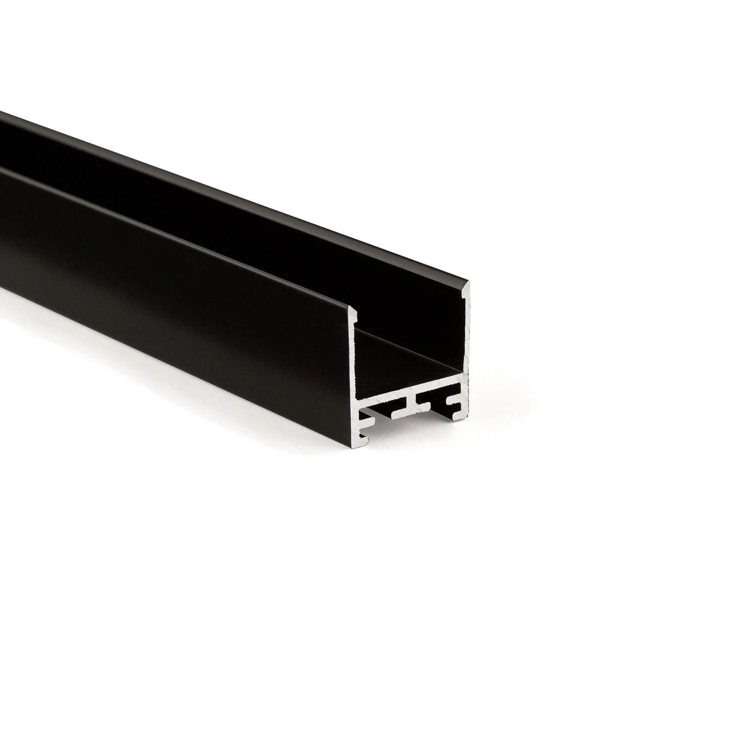
LL25 profile – the all-round visible profile
Consistent design language for recessed, surface-mounted and pendant installations
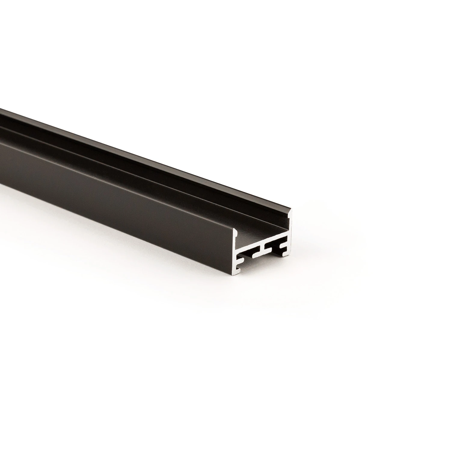
Visible profile LL2515
Compact aluminium body with sculptural V5 cover
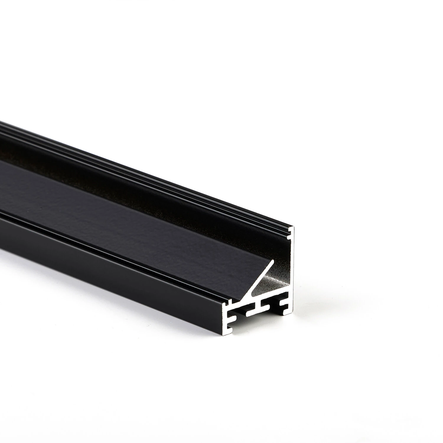
Corner visible profile LL2511E
45° inclined light-emitting surface for targeted aiming
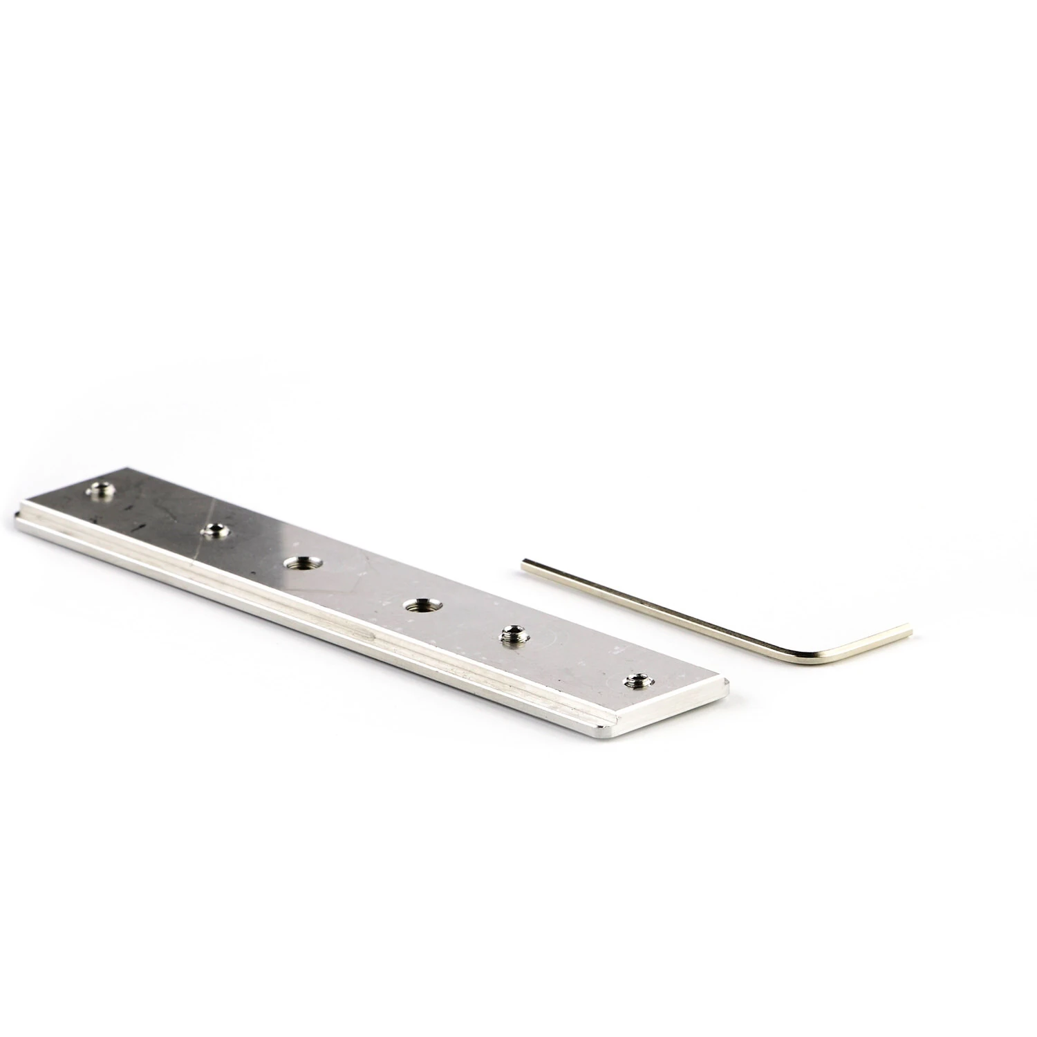
Mounting base plate and molded parts
Different connection directions
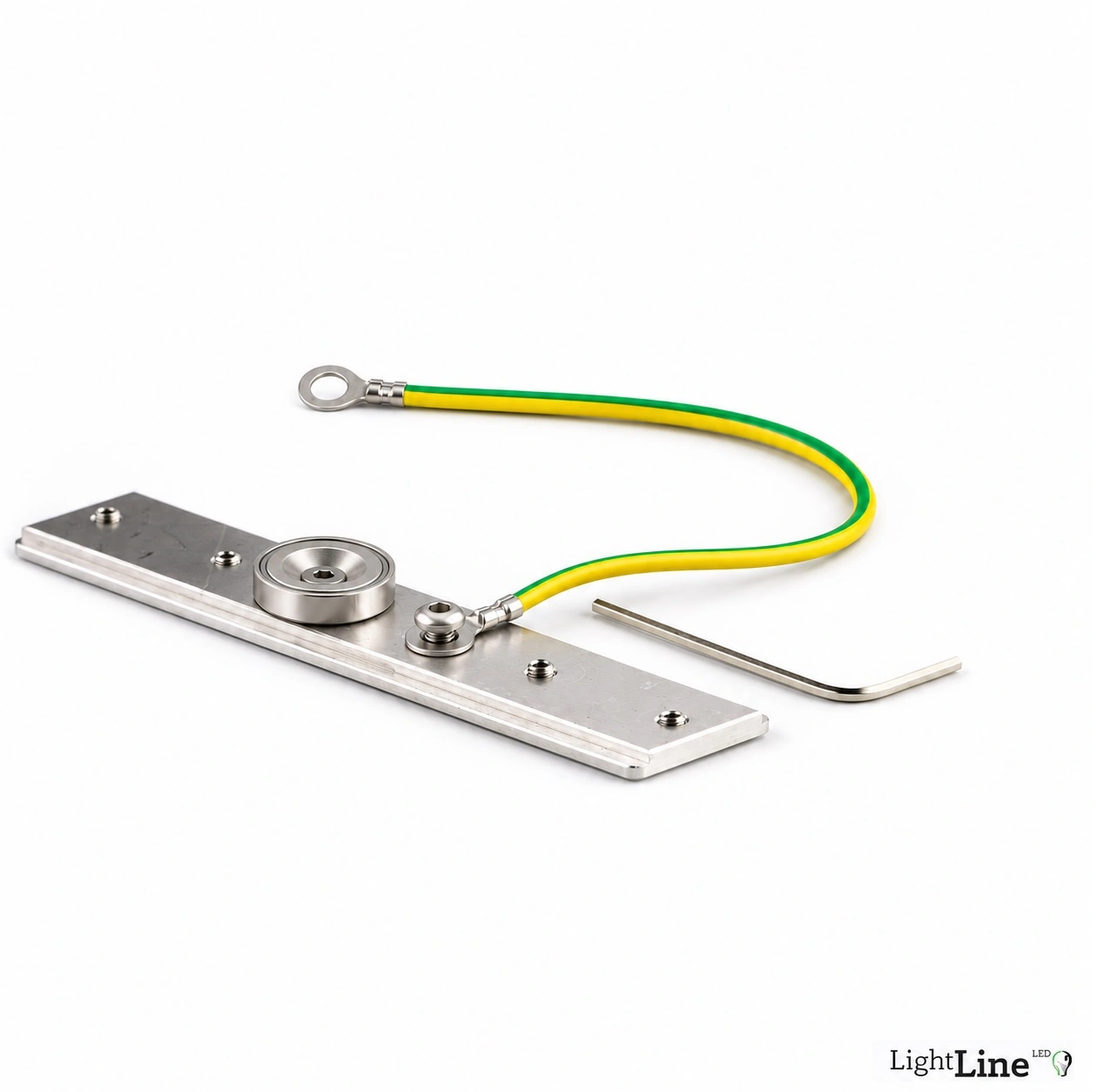
Mounting magnet with independent safety retention
Removable mounting on suitable steel
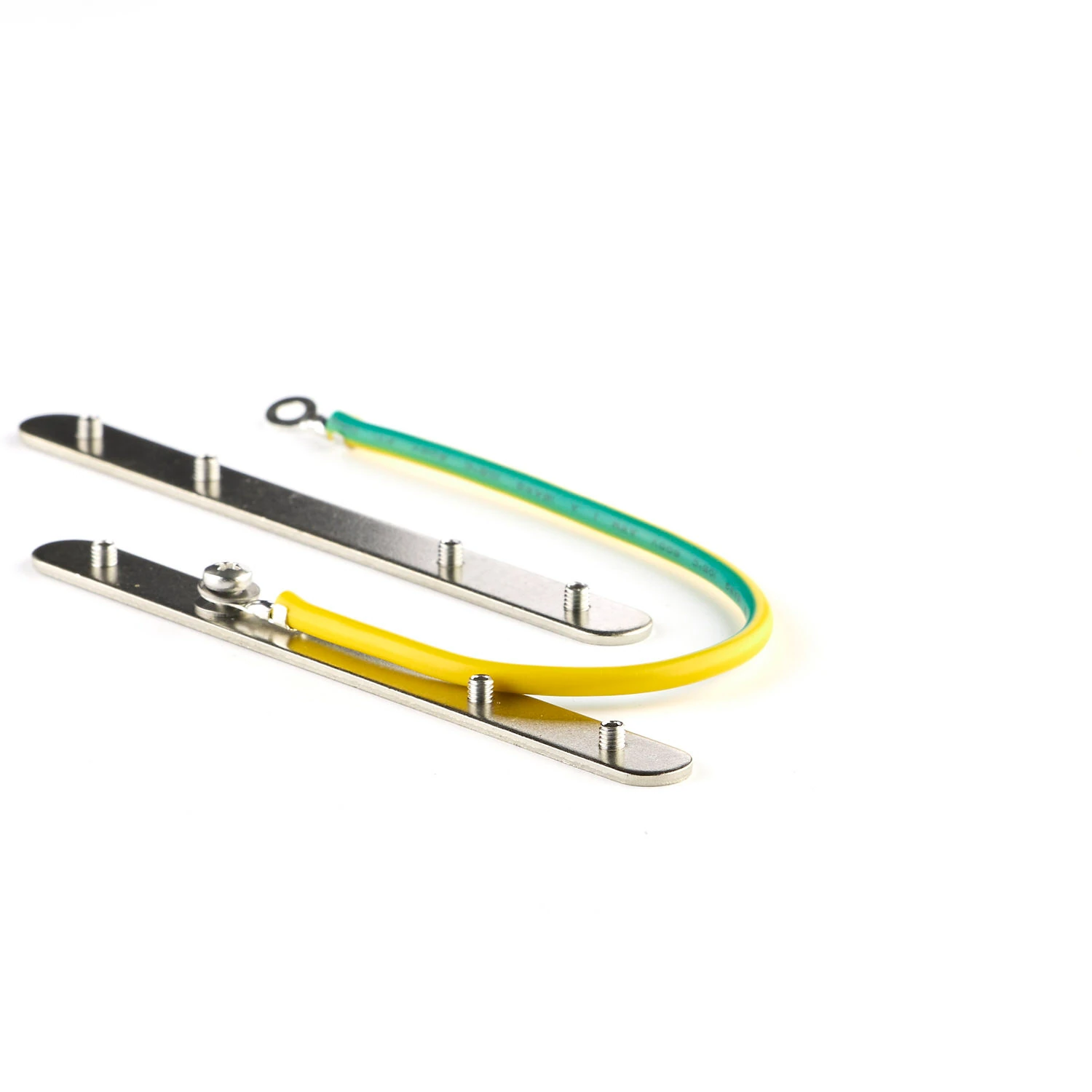
Fall protection for surface-mounted and pendant use
Connecting and securing at the profile joint
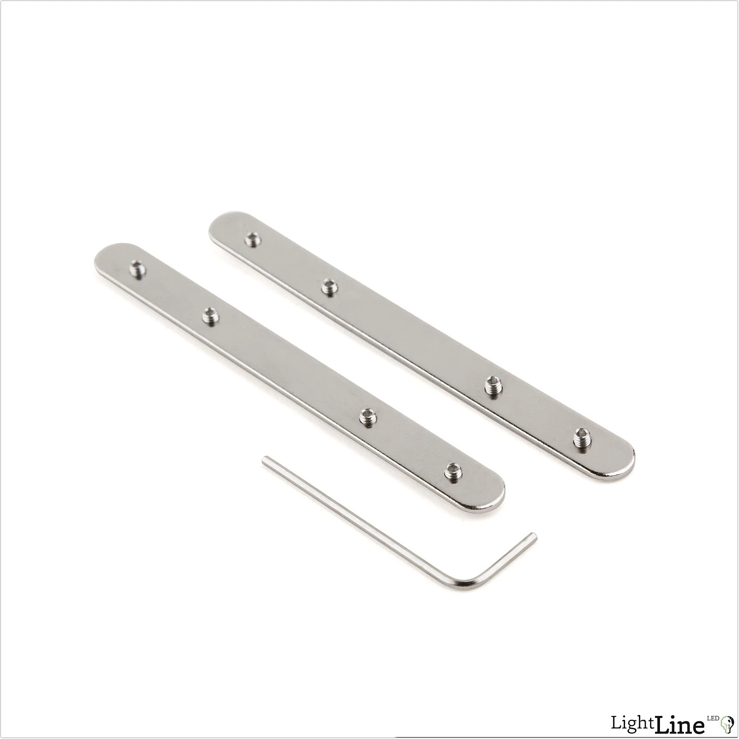
Profile connectors for lines and angles
Straight and three-dimensional profile transitions
Light line found.
We'll clarify the details together.
Building material, surface and desired lighting effect set the direction. MPW supports you with the right system version and the next steps.
More possibilities for your architecture.
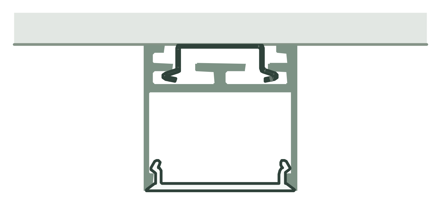 14
Surface mounting
Surface-mounted with metal clip, cavity spring or LL2509 as mounting base.
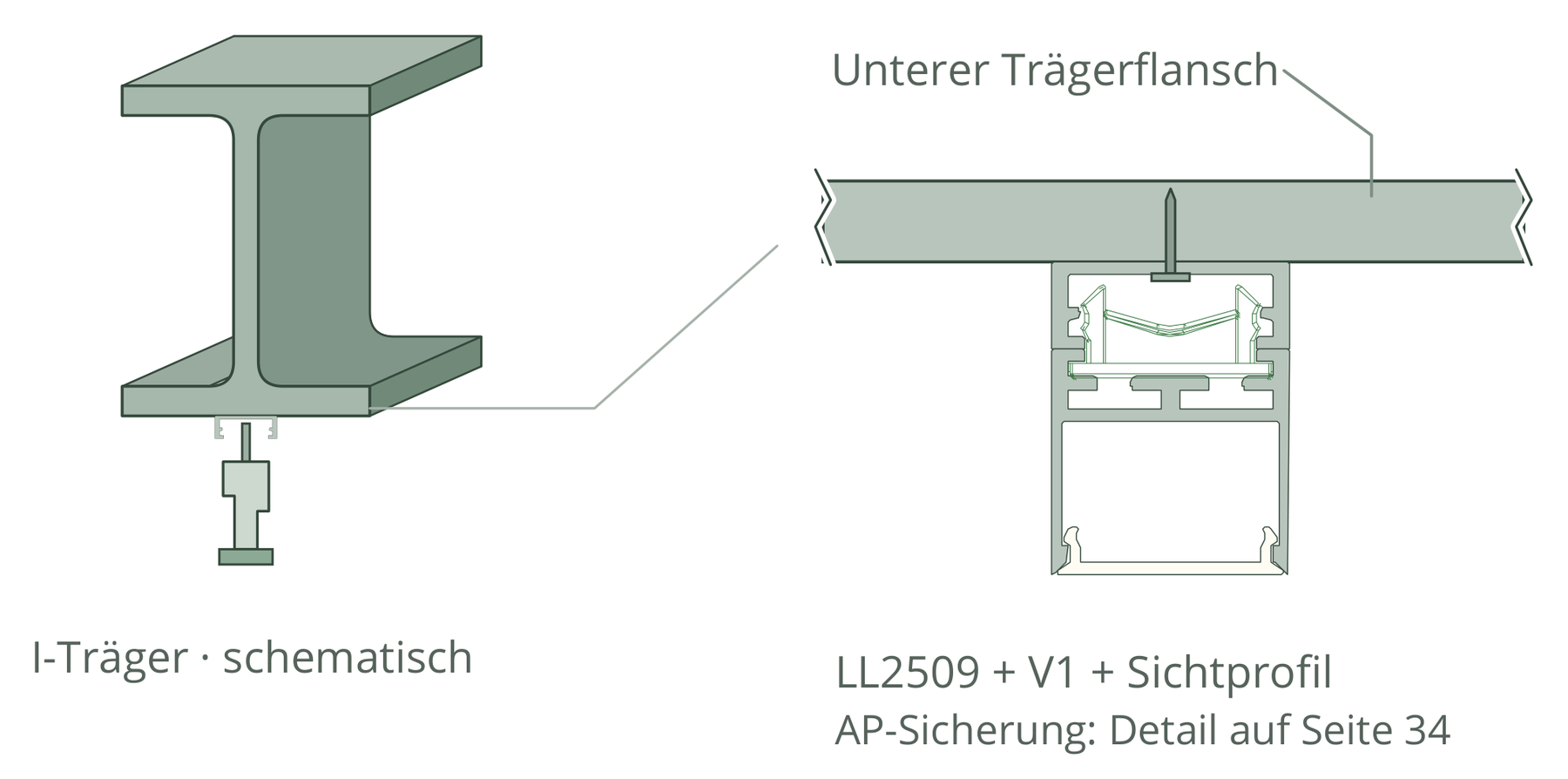 15
LL2509 as a multi-profile
Mounting base, mini light profile or blind cover: one component, several tasks.
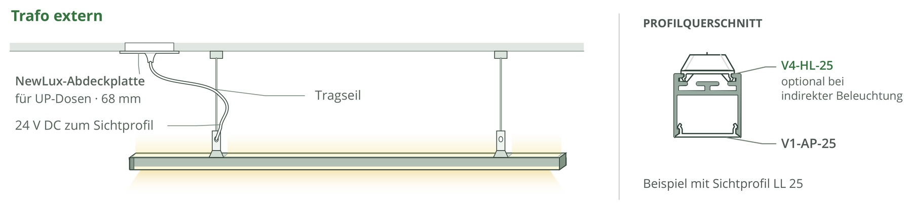 16
Suspended light lines
Slender pendant luminaires with external, separate or integrated technology.
Light lines in architecture.
Discover implemented LightLineLed solutions in different rooms and building materials.