

From components
to a lighting solution.
Good lighting design combines the desired light with the right profile, a suitable power supply and the conditions at the installation location.
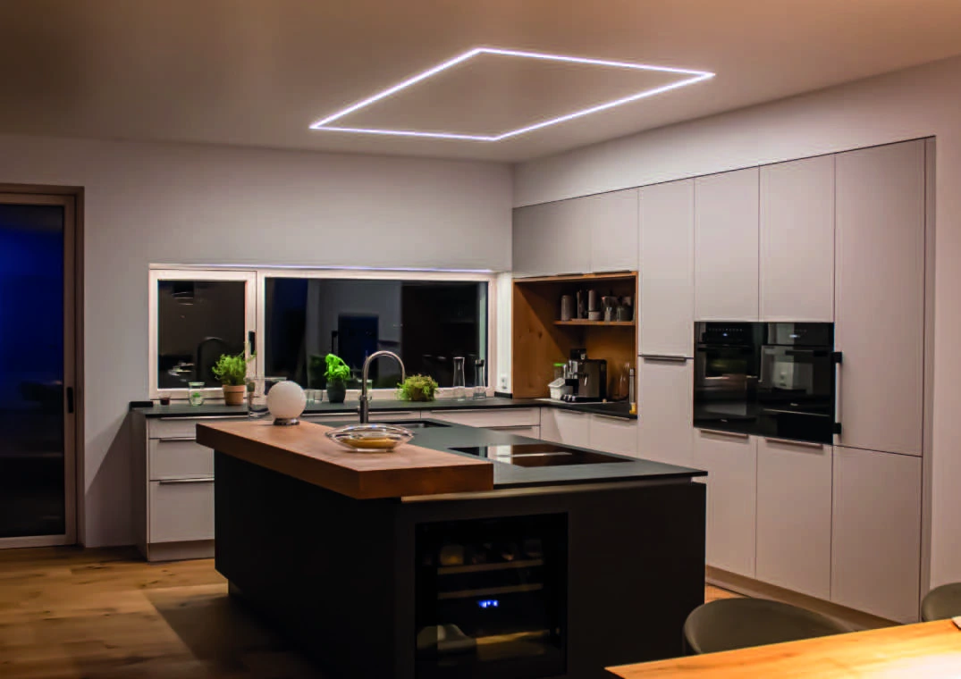
Light colour, colour rendering and light distribution.
| Planning dimension | What it means for the light line |
|---|---|
| Light colour / CCT | A fixed colour temperature creates a defined white-light effect. Tunable-white strips allow changes within the range of the specific article. |
| Colour rendering / CRI | Use the CRI of the selected strip or finished luminaire; do not adopt it from another series. |
| Luminous flux | Distinguish strip values from values of the finished luminaire. Profile, cover and fitting influence the usable luminous flux. |
| Light distribution | Cover and installation determine where the light lands. Use the matching photometric data set for lighting calculations. |
| Line length and shape | Coordinate the strip's cut pitch, profile joints, end caps and feed-in points early with the desired visible geometry. |
The W/m belong to the whole assembly.
The nominal strip power is a starting point. What matters is how much power the specific profile and cover combination can continuously dissipate at the installation location.
The connected load of a strip section results from its length and its power per metre. For selecting the control gear, device-specific load limits, ambient temperature and, where applicable, derating are added.
Depending on supply voltage and output, different currents result. Feed points, cable lengths and cross-sections influence the voltage drop and thus the uniformity of the lighting effect. The permissible electrical strip length is given in the data sheet of the specific series.
| Check step | Required information |
|---|---|
| LED strip | Voltage, W/m, strip width, cut pitch, maximum section, Tc/Ta and protective build-up. |
| Driver / power supply | Output type and voltage, permissible load, installation height, installation position, protection rating and environment. |
| Controller / control | Interface, channel count, current per channel and permissible total load. |
| Cable / feed-in | Length, cross-section, current, voltage drop and connection type of the planned runs. |
| Luminaire build-up | Profile, cover, installation situation, air movement, potting and inspection. |
LDT data matched to the fitting.
MPW provides photometric data for specifically measured lines of light. They describe the light distribution and help with project calculations.
The verified data set contains twelve designated 1 m combinations at 3000 K. The assignment covers the respective profile, strip and cover. A data set is only suitable if this configuration matches the planned luminaire.
All following measurements apply to a 1 m luminaire, anodised profile, opal cover and 3000 K nominal colour temperature. Nominal power and actually measured power are stated separately. Luminous flux and CRI come from the corresponding test reports.
| Profile & cover | Identifier | Rated power | Measured | Luminous flux | CRI | Photometric data |
|---|---|---|---|---|---|---|
| LL 25 V1, opal | 201150 | 10 W | 9.8 W | 521 lm | 94,6 | Download LDT |
| LL 35 F V1, opal | 201152 | 10 W | 9.8 W | 509 lm | 94,2 | Download LDT |
| LL 2515 V5, opal | 201155 | 10 W | 9.8 W | 514 lm | 94,2 | Download LDT |
| LL 2511 E V6, opal | 201157 | 10 W | 9.8 W | 527 lm | 94,2 | Download LDT |
| LL 25 V1, opal | 201190 | 15 W | 13.4 W | 829 lm | 93,5 | Download LDT |
| LL 35 F V1, opal | 201192 | 15 W | 13.4 W | 784 lm | 93,7 | Download LDT |
| LL 2515 V5, opal | 201195 | 15 W | 13.4 W | 791 lm | 93,9 | Download LDT |
| LL 2511 E V6, opal | 201197 | 15 W | 13.4 W | 820 lm | 93,9 | Download LDT |
| LL 25 V1, opal | 201230 | 22 W | 21.3 W | 1078 lm | 93,3 | Download LDT |
| LL 35 F V1, opal | 201232 | 22 W | 21.6 W | 1039 lm | 93,4 | Download LDT |
| LL 2515 V5, opal | 201235 | 22 W | 21.6 W | 1030 lm | 94,0 | Download LDT |
| LL 2511 E V6, opal | 201237 | 22 W | 21.6 W | 1059 lm | 93,5 | Download LDT |
A different length, light colour, strip configuration, cover or full potting may require different lighting data. For a deviating configuration, request the matching lighting data from MPW.
Installable, testable and accessible later.
Technical rooms should not only house the device. Connections, bending radii, heat dissipation and the removal path need space. With suspended solutions, the ceiling outlet, strain relief and cable routing are part of the design.
Mechanical securing follows the current installation chapter. With V2/V3 mounting clips, after shortening both lateral legs must again taper inwards to a point like the original tips; straight or blunt ends lead to breakage when snapping in.
Light line found.
We'll clarify the details together.
Building material, surface and desired lighting effect set the direction. MPW supports you with the right system version and the next steps.