

Track systems in the flush (UP) profile
One line, different lighting tasks. Combine linear light with spots, pendants or wall washers in a prepared system receptacle.
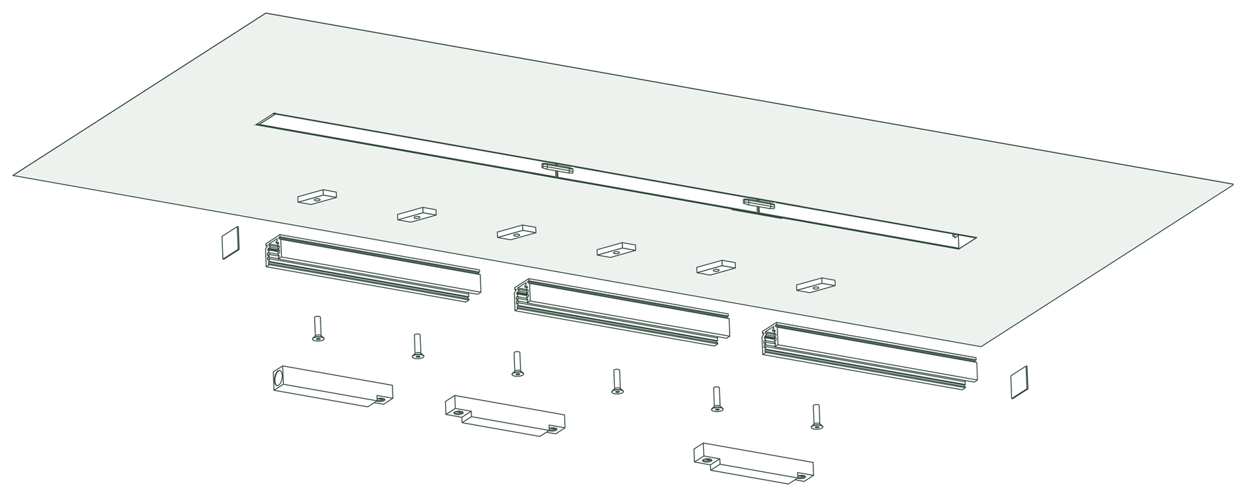
What this solution makes possible.
One housing, different lighting tasks: in suitable recessed profiles, LightLineLed lines of light can be combined section by section with NewLuxLed track systems. Spots, pendants and wallwashers complement the linear lighting – each with its own matching power supply.
Line of light and directional track luminaires within a prepared system housing.
Suitable installation principle for concrete, plaster, plasterboard, clay, timber and CLT indoors.
Documented versions for 48 V DC and single-phase 230 V AC.
This is how your line of light is made.
Application, construction and benefits – tailored to your architecture.
Combine linear light and targeted accents
Some rooms need directional light in addition to a continuous light line. In suitable LightLineLed UP profiles, linear sections can be combined with matching busbars. System-compatible spots, pendant luminaires or wall washers then complement the basic idea of the integrated line with further lighting tasks. This creates options for areas where individual objects, tables or wall surfaces are to be specifically lit. The shared structural housing joins the different sections into a planned run within the architecture.
A prepared channel in various building materials
The installation principle can be combined with suitable housings for concrete, plaster, plasterboard, clay and timber in interior spaces. The profiles are prepared together with the respective fit-out. The rail height and its fixing are based on the finished surface and the intended luminaires. This allows the design to coordinate the desired lighting effect with the building material early on. The rail is firmly screwed in place; it has its own role within the system and is not height-adjusted via mounting clips like a light line insert.
Choose the matching track system deliberately
The documented solutions include 48 V DC and 1-phase 230 V tracks. Both open up different options for the choice of associated luminaires and power supply. The decision is therefore made together with the desired lighting task. MPW offers suitable tracks and luminaires under the independent technology brand NewLuxLed. A shared profile housing does not mean a shared electrical supply: track and light line each receive the components required for the selected system.
Bringing lighting tasks in the building together
The benefit lies in the combination: one line can visually connect the room, while matching rail sections allow additional accents. Power supply, luminaire load and later access are taken into account during preparation. For 48 V, a suitable accessible transformer is planned in; the 1-phase rail has a different supply concept. The sections make these structural relationships visible and help define the desired combination with the lighting design and the executing contractor.
The solution in section
The system as construction progresses.
From the prepared housing to the finished light line.
The path to the finished light line
Define the system and installation position
Plan the finished surface, rail height, luminaire load and power feed. For 48 V, provide a suitable accessible 48 V transformer in the technical area.
Mount the flush-mount receptacle
Follow the installation instructions that match the building material. Keep the profile opening clean and the planned fixing points accessible.
Fix the rail with the power off
Position the angled nuts and fasten with suitable threaded screws. Use any spacers only after checking the bearing surface, screw length, thread engagement, installation height and load.
Complete electrics and luminaires
Install system-compatible feeders, connectors and end caps. Insert and lock matching luminaires; check mechanical hold and electrical protective measures.
Installation & documents.
The installation and processing instructions accompany the actual implementation of your line of light.
Track systems in the flush (UP) profile · Installation & processing
PDF · matching instructions
Safety and installation notes
PDF · observe together with the instructions
The complete installation manual
All applications and system details
Processing notes in detailMounting clips, safety cable and further notes on the specific design
Build-up details
The concrete-embedded profile and the plaster-in profile with 13 mm flange are particularly suitable.
The 48 V rail shown is four-pole, the single-phase 230 V rail two-pole. Mechanical fixing is done with angled nuts and threaded screws.
The rail is screwed firmly in place. Stepless height adjustment via LightLineLed mounting clips is not intended for it.
Processing and installation
Mounting clips V2 (20 mm) and V3 (30 mm) may be shortened. Afterwards, both side legs must again taper inwards at an angle and form tips like the original tips. Blunt or straight-cut leg ends cause the clips to break when snapping in. Bevel both legs accordingly, deburr the cut points and check the tip shape before installation. Then check for full snap-in seating and secure hold. Do not use damaged clips. No blanket shortening dimension or cutting angle.
48 V DC requires a matching 48 V driver; a 24 V driver is unsuitable for this. The 1P track is supplied with 230 V AC without a 48 V driver.
Run the 230 V supply cable fully enclosed and protected up to the feed-in unit; no open 230 V wiring in the flush (UP) profile.
The shared mechanical housing does not mean a shared electrical connection between 48 V, 230 V and the LED light line. Transfer loads, including pendants, into the load-bearing substrate.
Mixed LightLineLed sections receive the clips and securing parts matching the visible profile.
Before cutting, measure the temperature of the profile and cover. Allow room for movement at joints and end caps for heating and cooling, and clip in the cover free of stress.
Discover the matching products.
Profiles, covers and accessories together make up your light line. The product pages show versions and matching combinations.
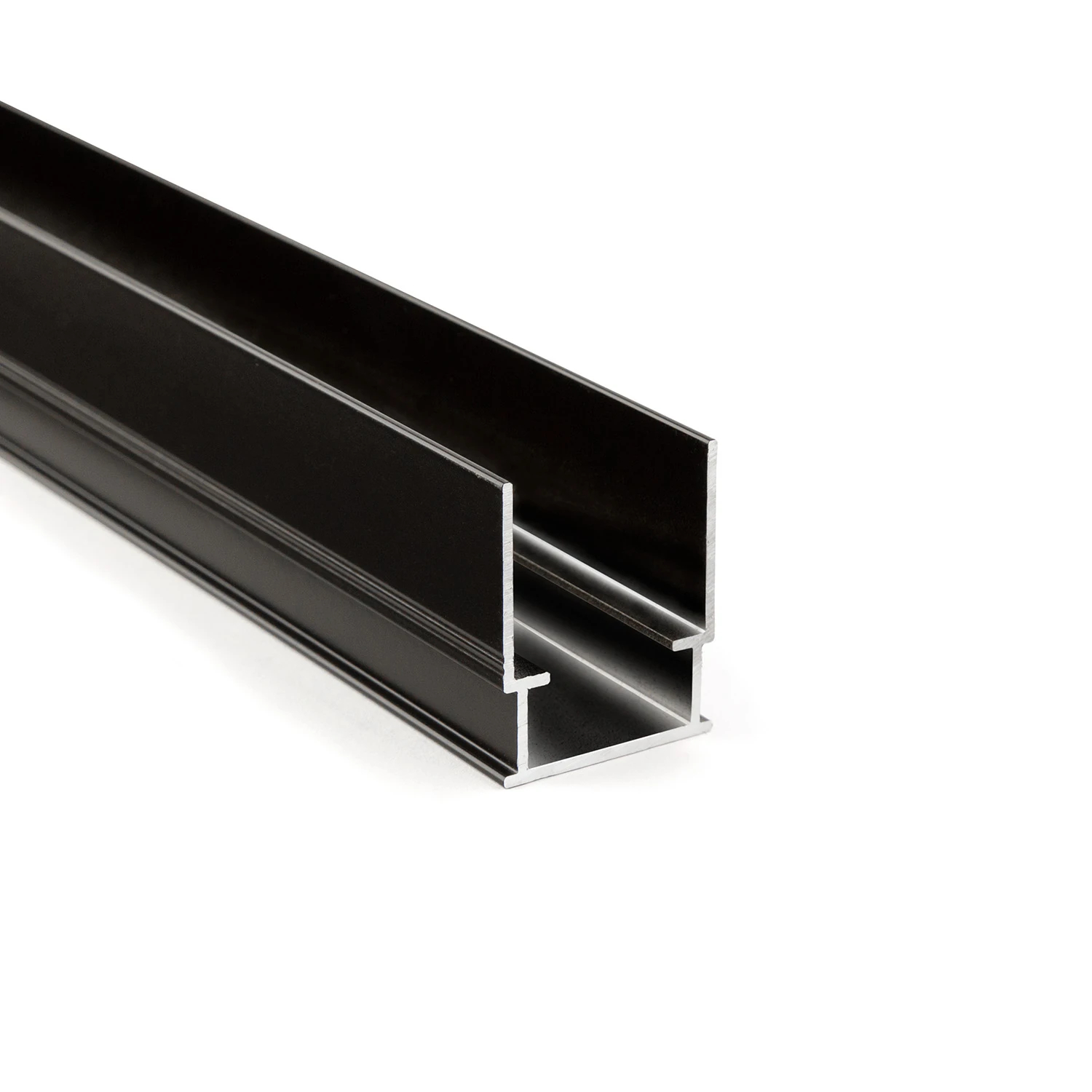
Concrete-embedded mounting profile
Prepare the light housing already in the in-situ concrete formwork
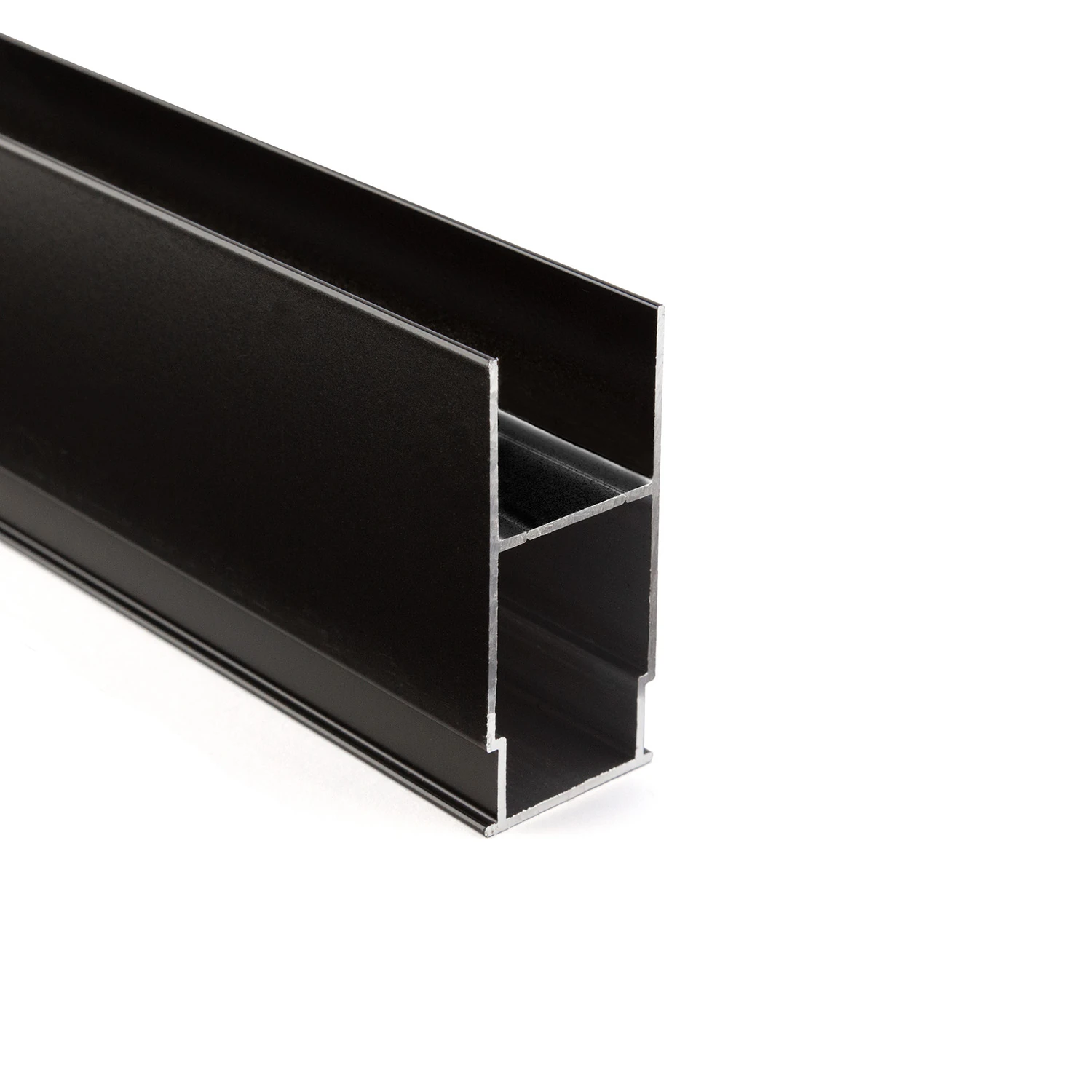
Concrete-embedded transformer profile
Supply technology accessible behind the luminaire insert
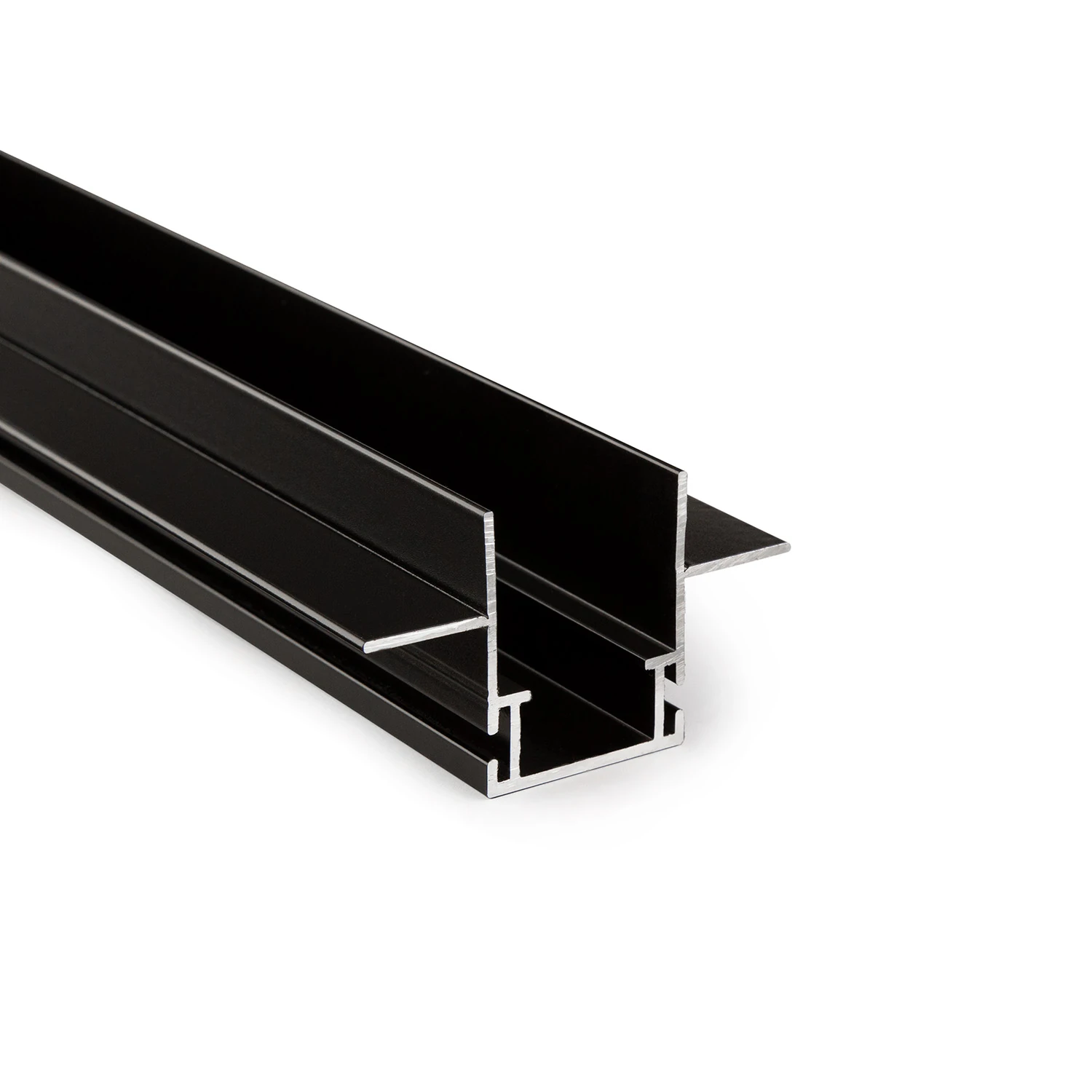
Mounting profile with 13 mm wing
Prepare the line of light together with the board cladding
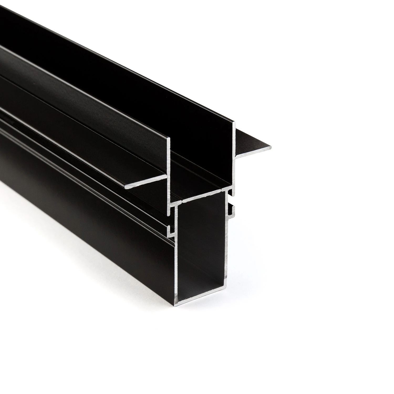
Driver profile with 13 mm flange
Power supplies and terminal points accessible via the light line
Light line found.
We'll clarify the details together.
Building material, surface and desired lighting effect set the direction. MPW supports you with the right system version and the next steps.
More possibilities for your architecture.
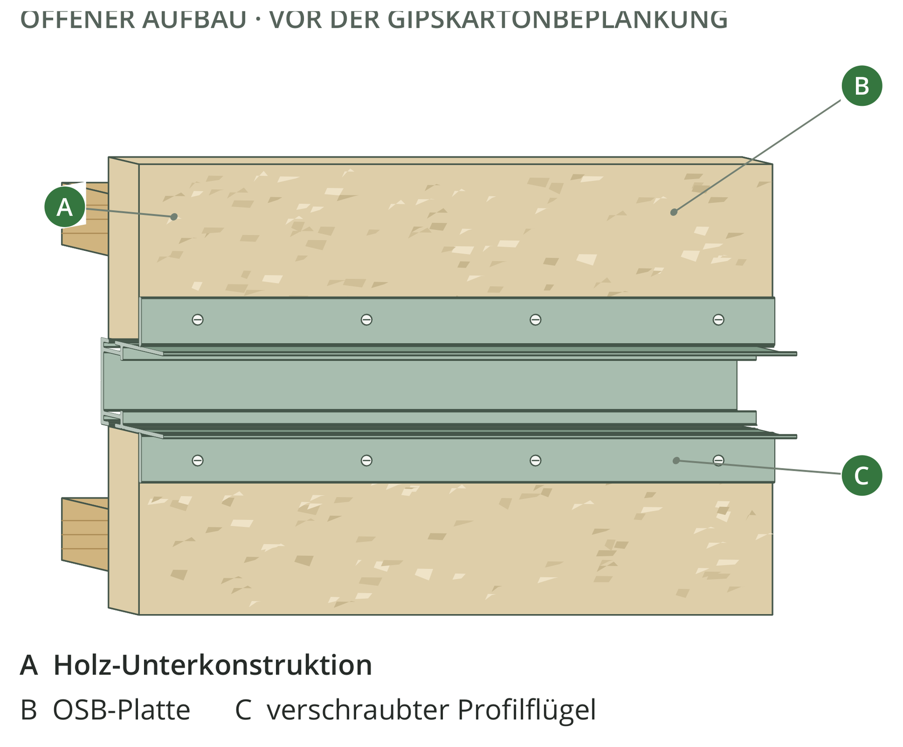 03
Timber construction with OSB & plasterboard
OSB, 12.5 or 15 mm plasterboard: the right detail for every layer.
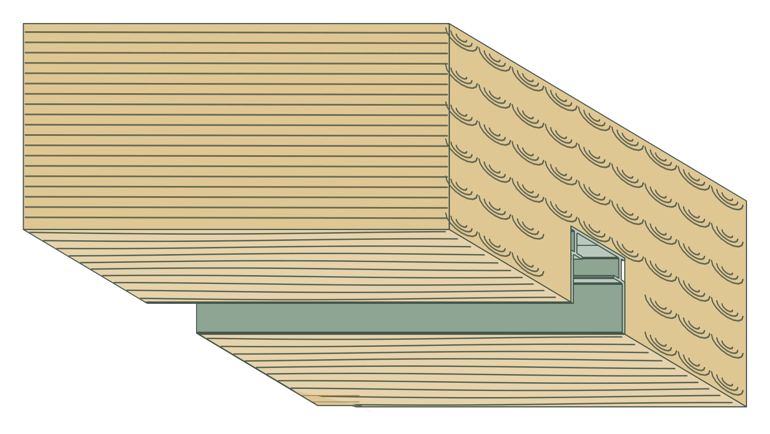 04
Solid wood & CLT
Precise routing and accessible light inserts in solid wood and cross-laminated timber.
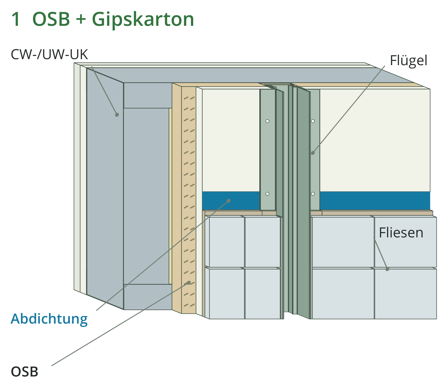 05
Tiled stud wall
Light between wall build-up and tile pattern. With a cleanly executed connection.
Light lines in architecture.
Discover implemented LightLineLed solutions in different rooms and building materials.