

Solid wood & CLT
The natural timber surface remains visible, and the light blends in. LightLineLed creates flush light lines in solid timber and CLT – for architecture with a clear material presence.
What this solution makes possible.
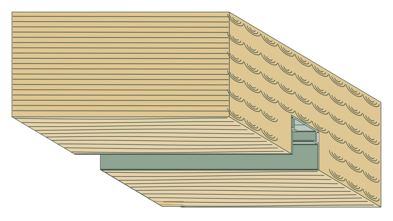
The wood remains visible, the light is integrated flush. In solid wood and cross-laminated CLT elements, the concrete recessed profile sits in a precisely fitted routed recess. An additional layer of plaster or plasterboard is not provided for in this detail.
The natural timber soffit remains the finished surface.
The profile housing and luminaire insert are installed separately.
Flush integration with lighting technology accessible later.
This is how your line of light is made.
Application, construction and benefits – tailored to your architecture.
The timber surface remains visible
A visible timber ceiling thrives on its material effect. LightLineLed adds an integrated light line to this surface without requiring an additional plaster or plasterboard layer. The profile receptacle sits in a matched milled recess of the solid timber or CLT element. The light can accompany room axes or highlight individual areas, while grain and timber surface continue to shape the room. The visible luminaire insert sets a clear, deliberately chosen termination in the timber.
Prepared to fit instead of improvised later
The shape of the routed recess depends on the actual profile contour and the associated connectors and end terminations. In this application, the concrete-installation profile is used as a channel in the timber and fixed through its back. Early coordination with the timber construction creates the basis for a clean visible edge. Solid timber and multi-layer CLT are considered according to their build-up; structure, cable routes and required technical space belong in the planning of the elements from the outset.
Design the visible line separately from the technology
Mounting and driver profiles allow different zones within the prepared run. The mounting profile receives the luminaire insert; the deeper driver zone provides space for suitable supply technology and connections. This allows the technical location and light output to be planned together, without each technical component determining the appearance of the timber soffit. The choice of visible profile, cover and suitable LED fit depends on the desired lighting effect and the permissible thermal operation.
A well-thought-out detail for installation and service
The fixed channel and the later luminaire insert remain separate components. This allows the light unit to be prepared and tested outside the finished timber surface. With a suitable removal path, it also remains accessible for later maintenance, while the installation profile stays in the timber. Sampling the connection helps to assess fit and visible joint in advance. The required routing and fixings are coordinated with timber construction and structural planning.
The solution in section
The system as construction progresses.
From the prepared housing to the finished light line.
The path to the finished light line
Coordinate routing and structure
Define position and depth with timber construction planning and structural engineering. Consider fire protection, sealing planes, cable route and the deeper transformer zone.
Check the fit on a sample
Produce the routed recess with minimal tear-out, check movement clearance and preserve the finished visible edge. Protect the profile and timber surface until fitting.
Fix the installation profile
Assemble profiles flush with the matching concrete connectors and fit end caps. Screw without tension; match fasteners, edge distances and screw-in depth to the timber and load.
Install light and keep it accessible
After the timber work, remove the protection and clean the channel. Connect the prepared light unit, secure it and insert it with suitable clips; the flush solution shown uses V1 at 10 mm.
Installation & documents.
The installation and processing instructions accompany the actual implementation of your line of light.
Solid timber & CLT · Installation & processing
PDF · matching instructions
Safety and installation notes
PDF · observe together with the instructions
The complete installation manual
All applications and system details
Processing notes in detailMounting clips, safety cable and further notes on the specific design
Build-up details
The concrete-embedded profile is fixed to load-bearing timber through its back. Screw heads must not obstruct the light insert.
Mounting profile 37 mm, driver profile 64 mm. Make the cut-out according to the actual profile contour, including end caps and concrete connectors.
Solid wood has a continuous grain direction; CLT alternates between longitudinal and transverse layers. The five-layer drawing does not specify a general component thickness.
Processing and installation
Mounting clips V2 (20 mm) and V3 (30 mm) may be shortened. Afterwards, both side legs must again taper inwards at an angle and form tips like the original tips. Blunt or straight-cut leg ends cause the clips to break when snapping in. Bevel both legs accordingly, deburr the cut points and check the tip shape before installation. Then check for full snap-in seating and secure hold. Do not use damaged clips. No blanket shortening dimension or cutting angle.
The retaining clip of the fall protection locks exclusively into the mounting profile, never into the flush-mount driver profile. If the light line begins with 0.5 or 1 m of driver profile, the upper securing fixing lies only in the adjoining mounting profile. A continuous flush-mount driver profile does not allow this type of securing; every lighting element must still be secured.
Four mounting clips per metre, rounded up and at least two per section. V1: 10 mm, V2: 20 mm, V3: 30 mm – choose to match the actual fit-out height. Secure visible profiles at the start, at every joint and at the end; the connector pair sits in both rear longitudinal slots of the suitable visible profile.
In the flush-mount driver profile, maximum driver installation height is 18 mm; remove the pull-out tab only after complete installation. MPW recommends routing the conduit in at the start of the driver profile, not through the end caps. Keep the electronics, terminal point and inspection access accessible.
The concrete recessed profile itself has no receptacle for the profile connectors of the fall-protection device. The connectors sit in the suitable visible profile; the concrete holder belongs in the mounting profile.
Before cutting, measure the temperature of the profile and cover. Allow room for movement at joints and end caps for heating and cooling, and clip in the cover free of stress.
Discover the matching products.
Profiles, covers and accessories together make up your light line. The product pages show versions and matching combinations.
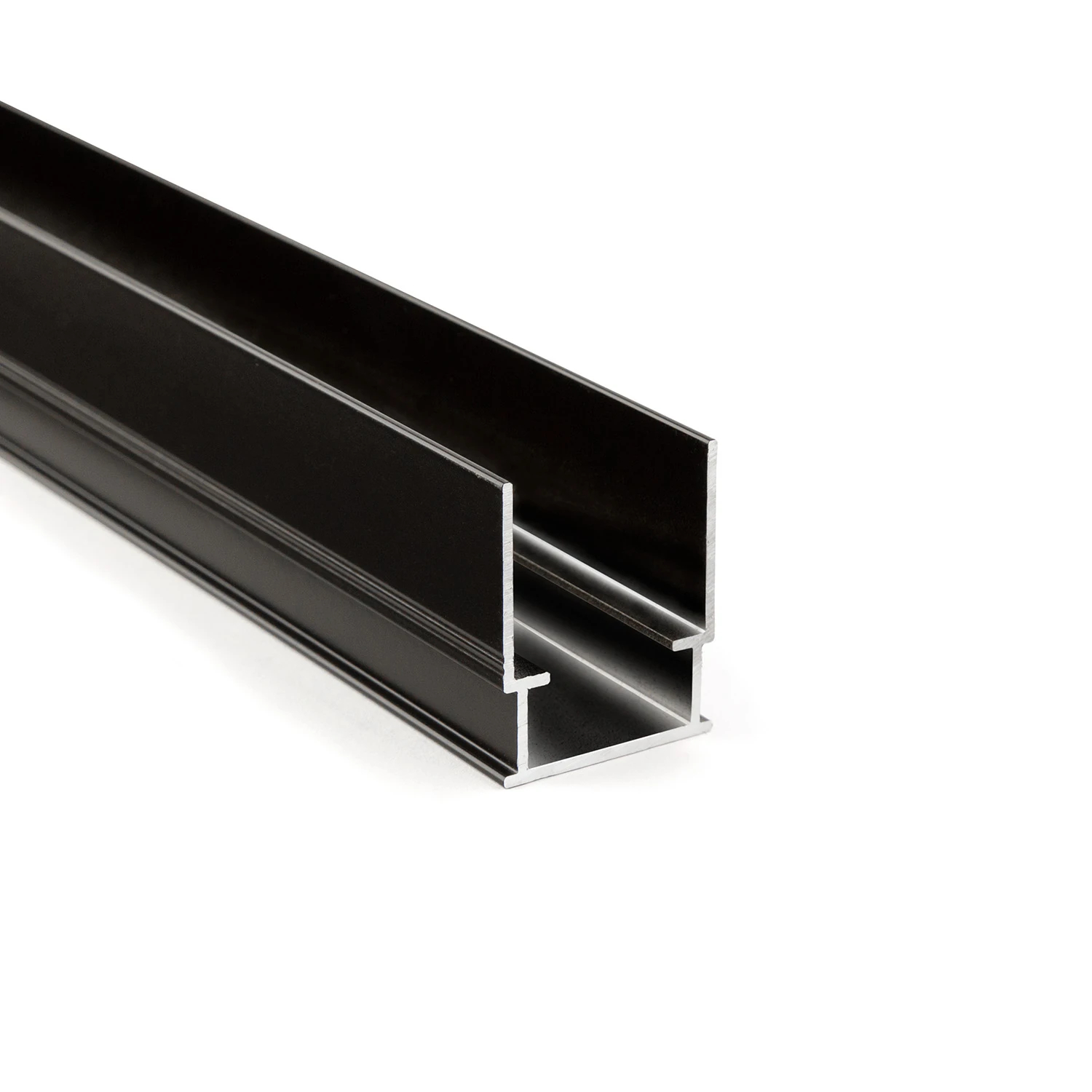
Concrete-embedded mounting profile
Prepare the light housing already in the in-situ concrete formwork
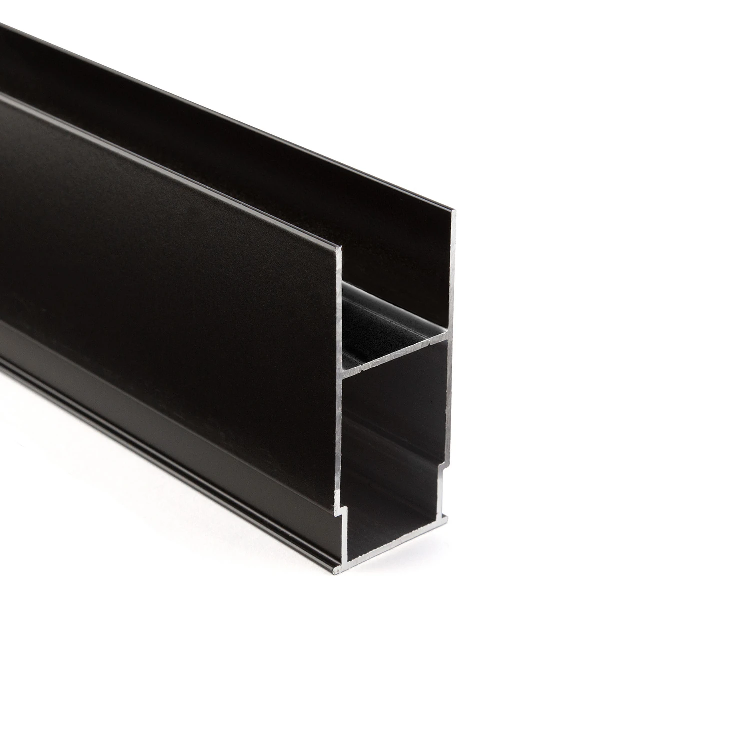
Concrete-embedded transformer profile
Supply technology accessible behind the luminaire insert
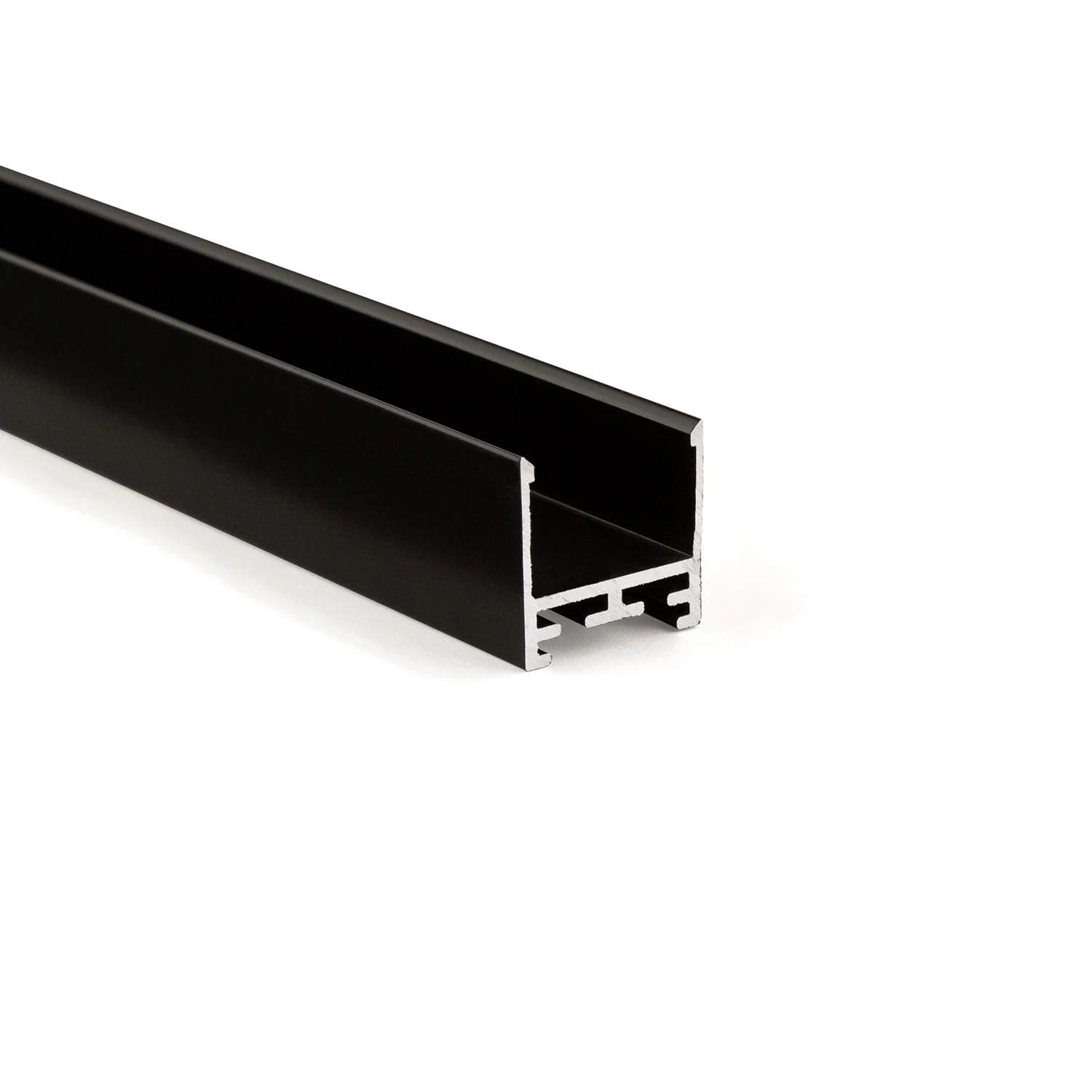
LL25 profile – the all-round visible profile
Consistent design language for recessed, surface-mounted and pendant installations
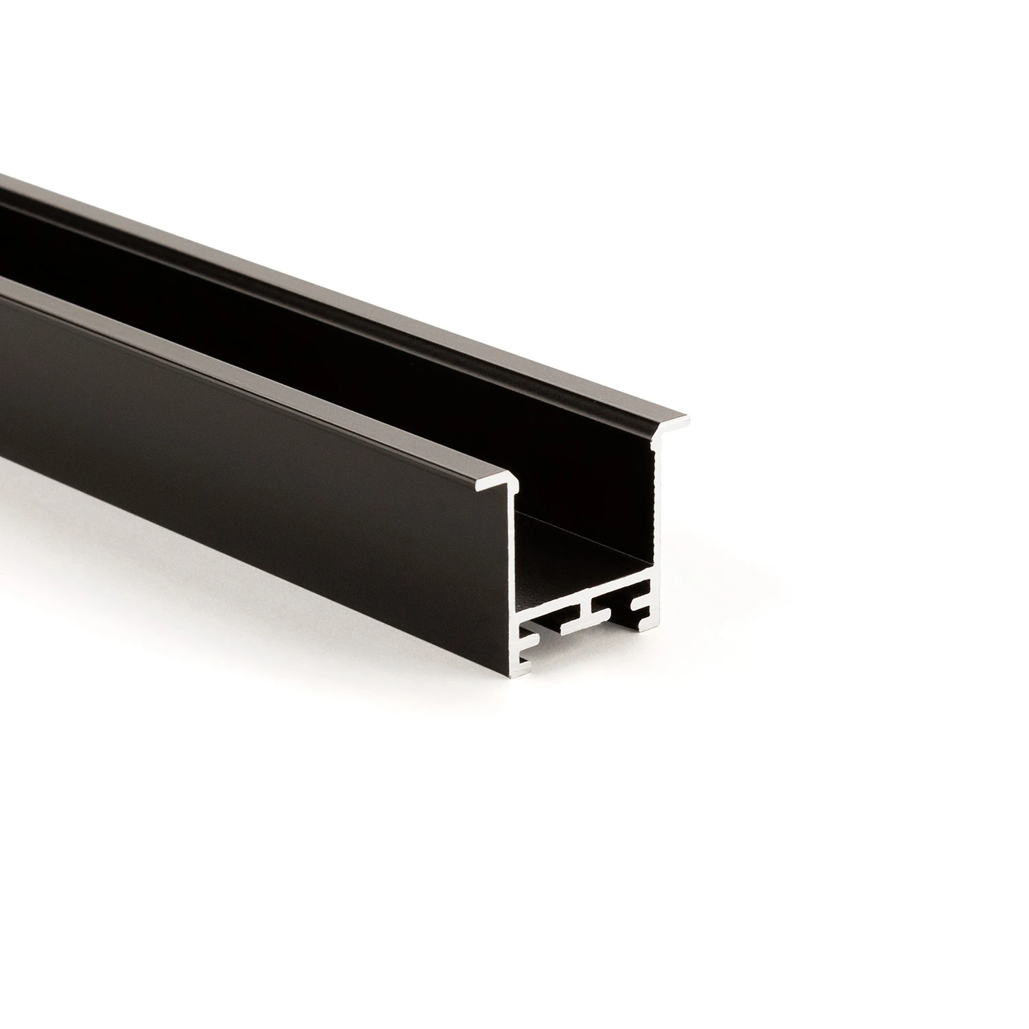
Recessed and visible profile LL35F
Visible aluminium edge covers the connection joint
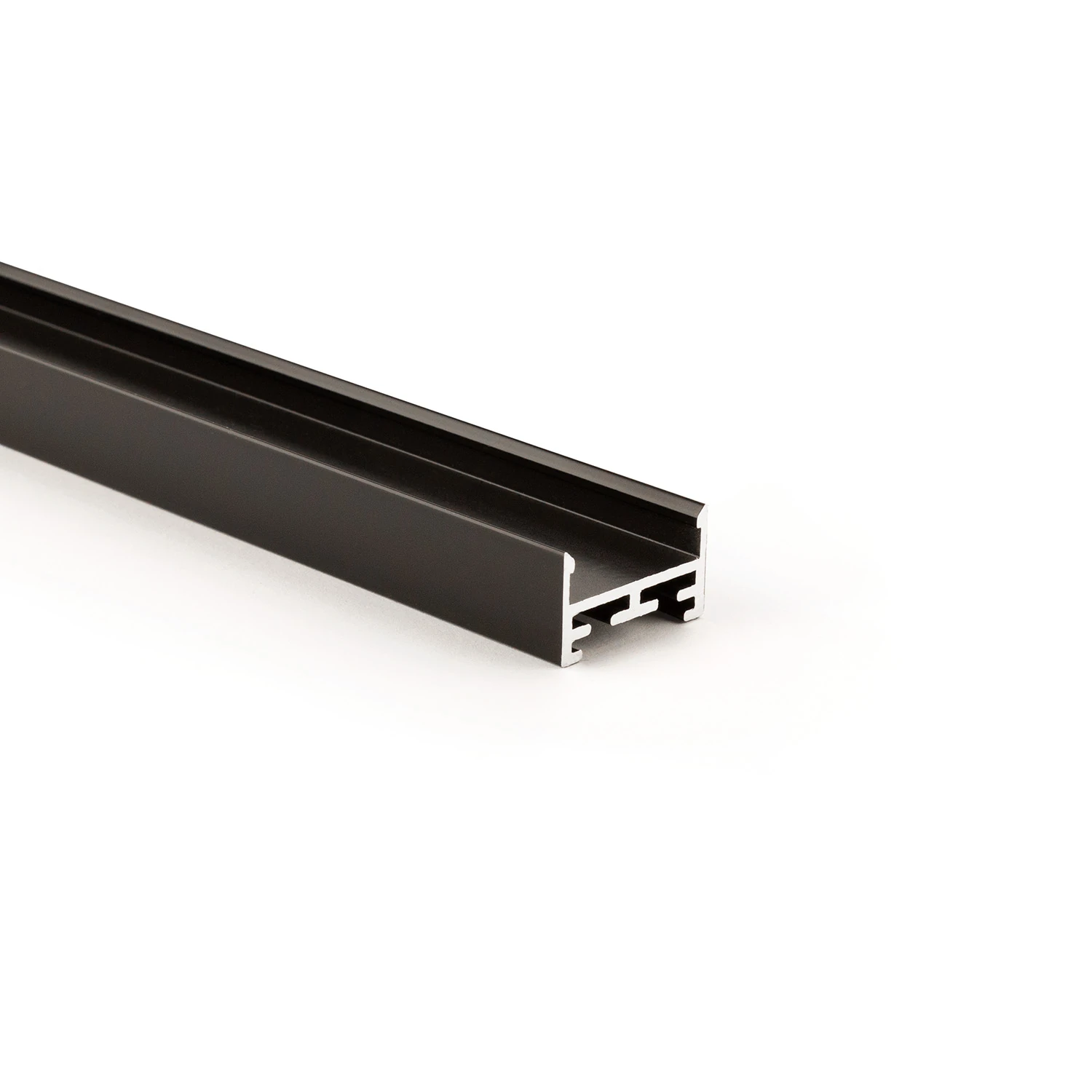
Visible profile LL2515
Compact aluminium body with sculptural V5 cover
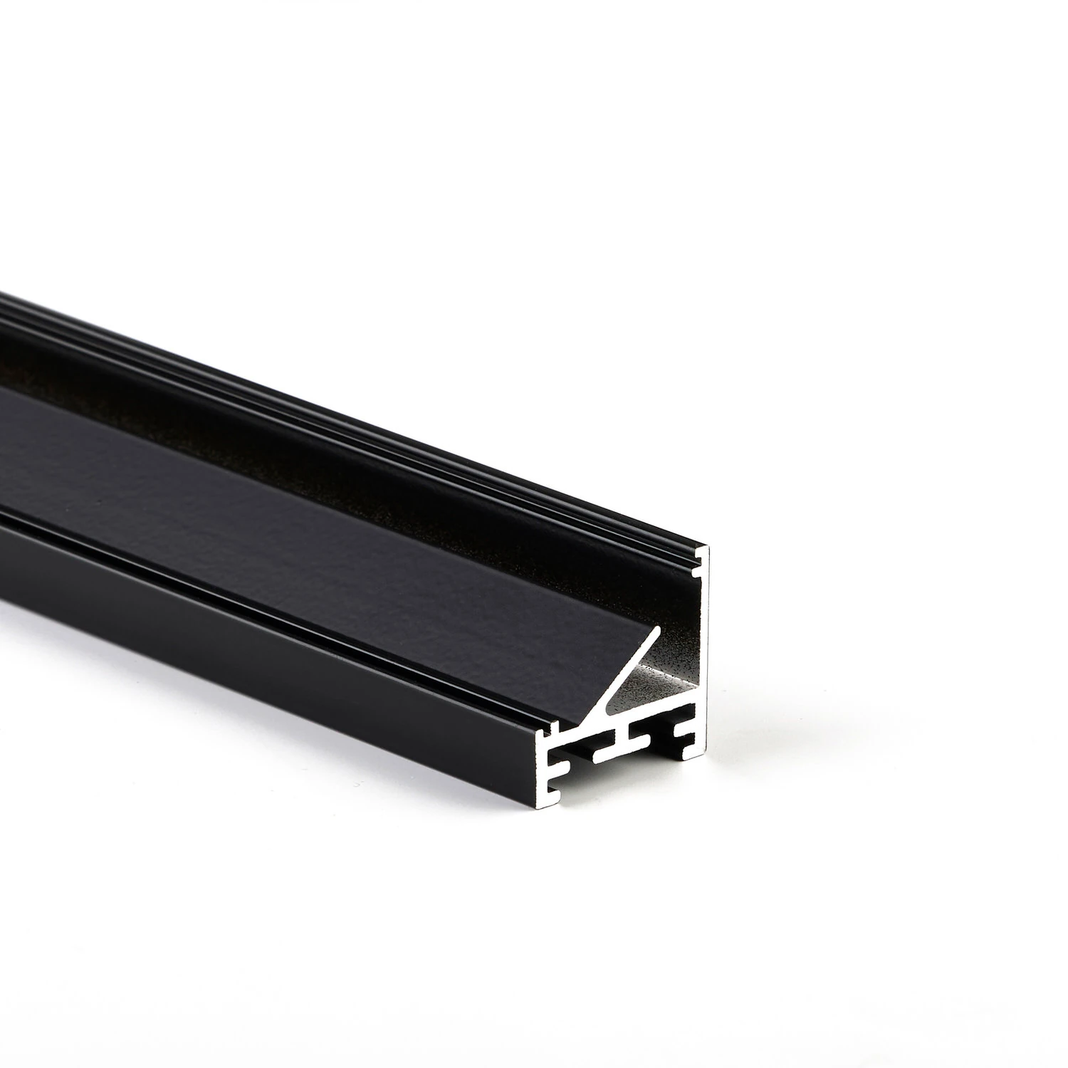
Corner visible profile LL2511E
45° inclined light-emitting surface for targeted aiming
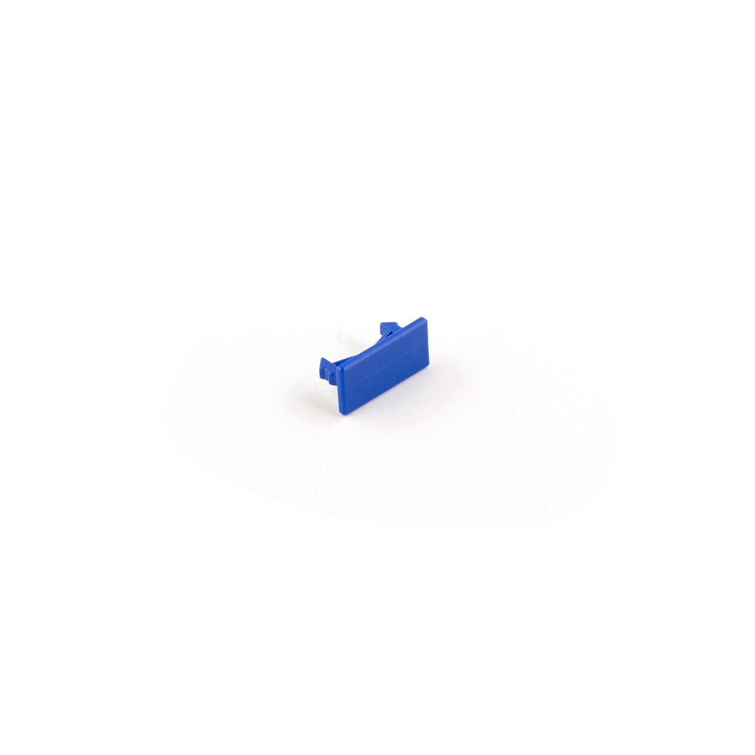
Mounting clips V1, V2 and V3
Height adjustment within the intended combination
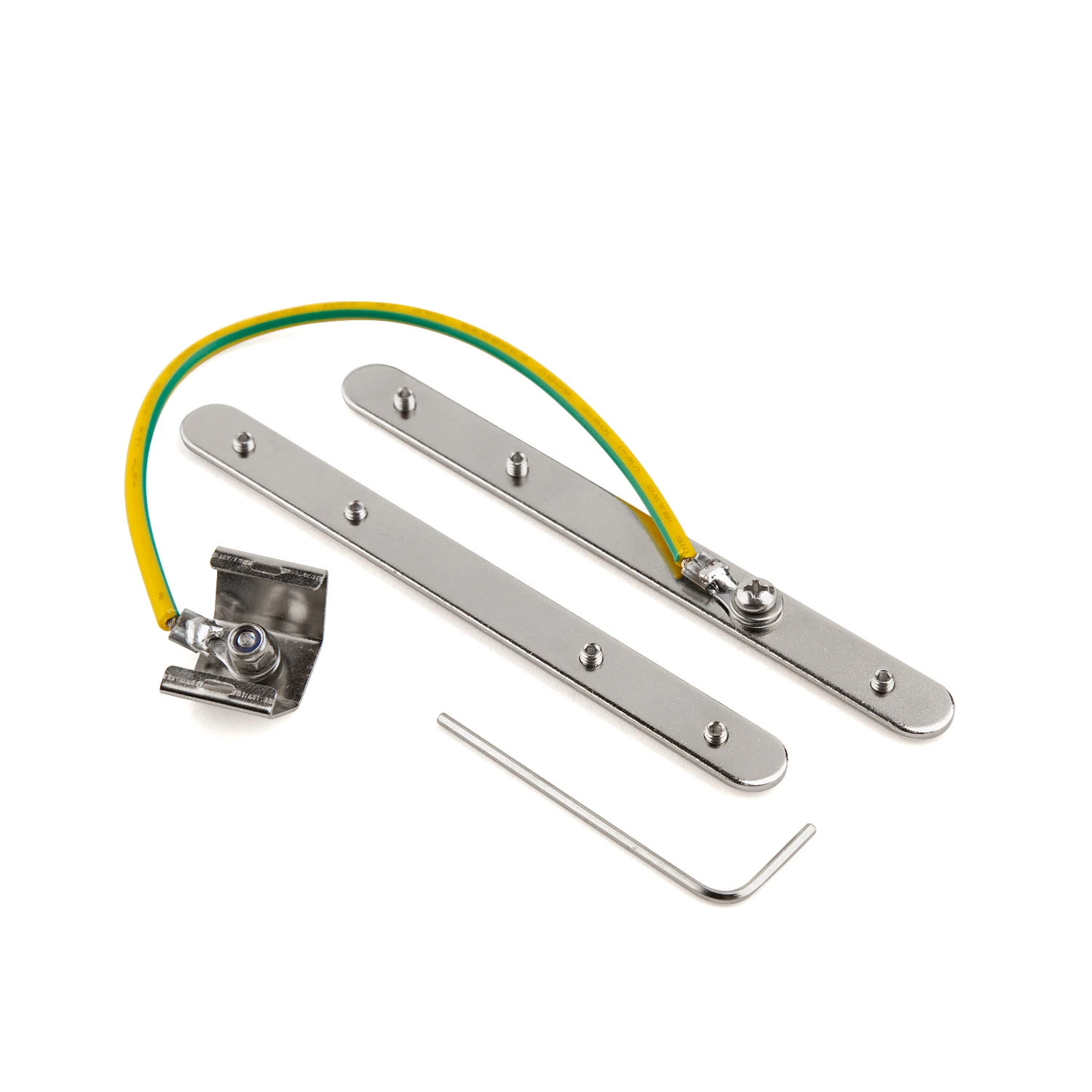
Fall protection for concrete installation
Connecting and securing at the profile joint
Light line found.
We'll clarify the details together.
Building material, surface and desired lighting effect set the direction. MPW supports you with the right system version and the next steps.
More possibilities for your architecture.
 03
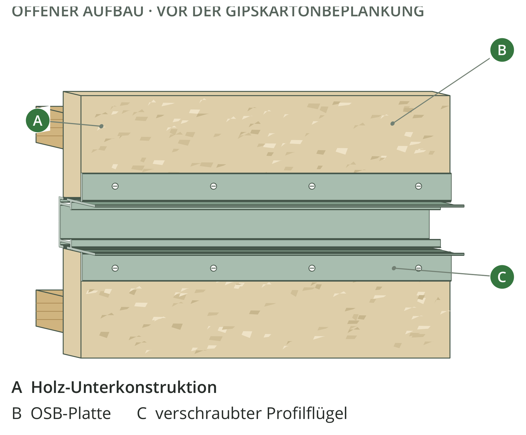
Timber construction with OSB & plasterboard
OSB, 12.5 or 15 mm plasterboard: the right detail for every layer.
 05
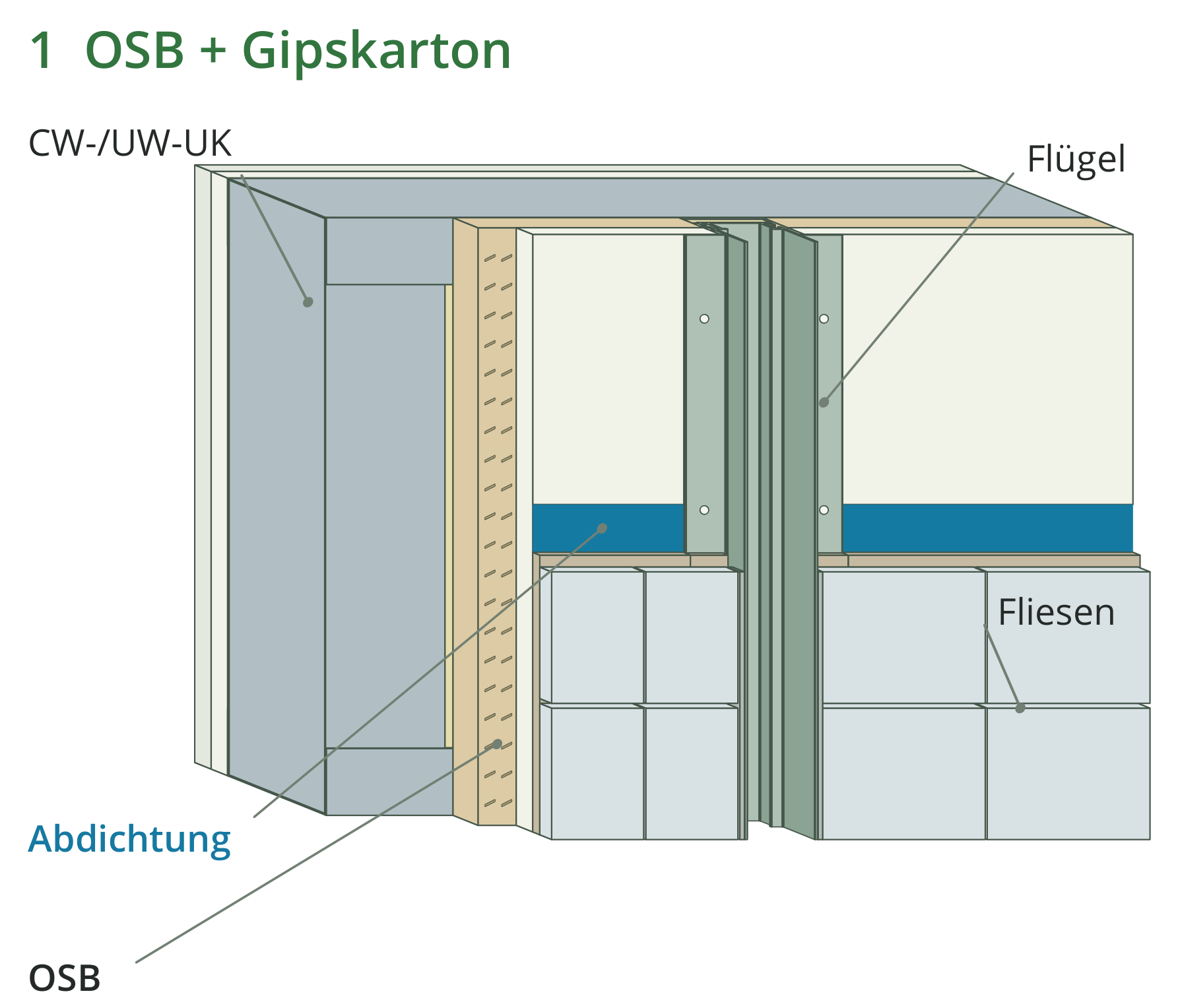
Tiled stud wall
Light between wall build-up and tile pattern. With a cleanly executed connection.
 06
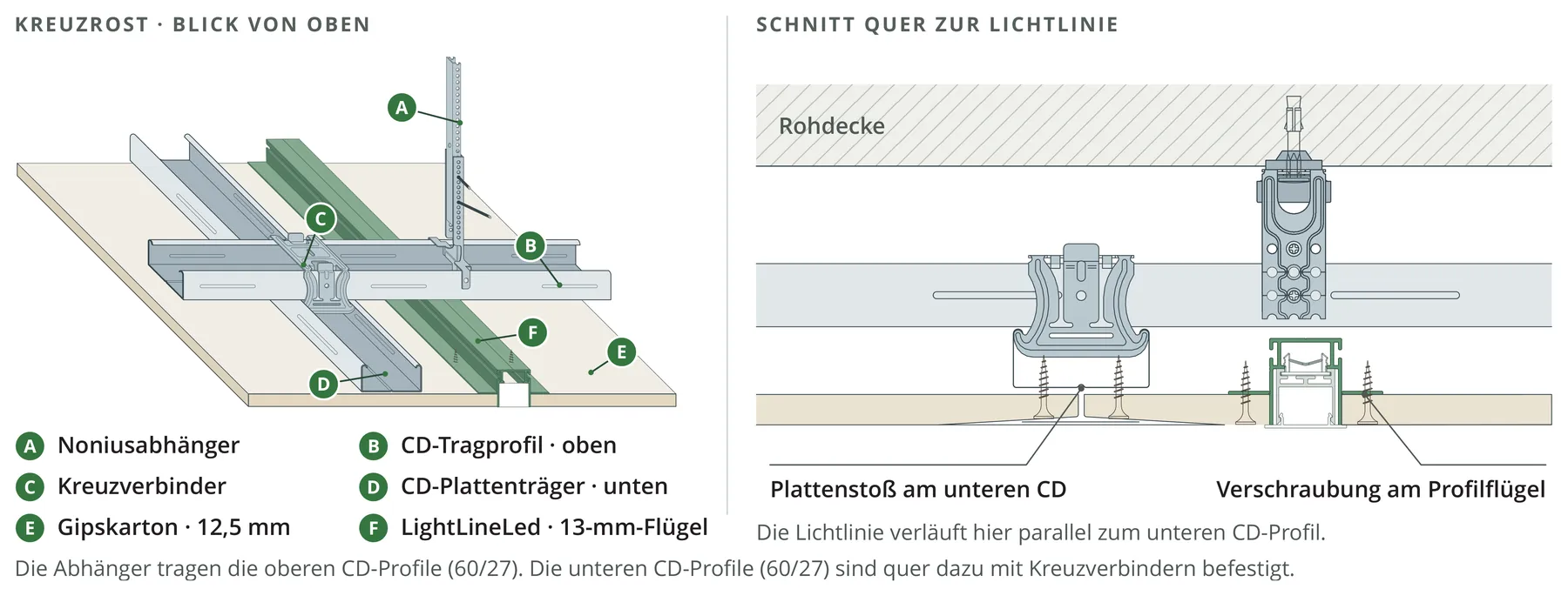
Plasterboard ceiling
13 mm wing profiles behind the cladding. For calm, integrated ceiling lines.
Light lines in architecture.
Discover implemented LightLineLed solutions in different rooms and building materials.