

ETICS fittings
Preformed insulation parts prepare the space for your light line. Mounting and technical sections can be combined into a continuous facade solution.
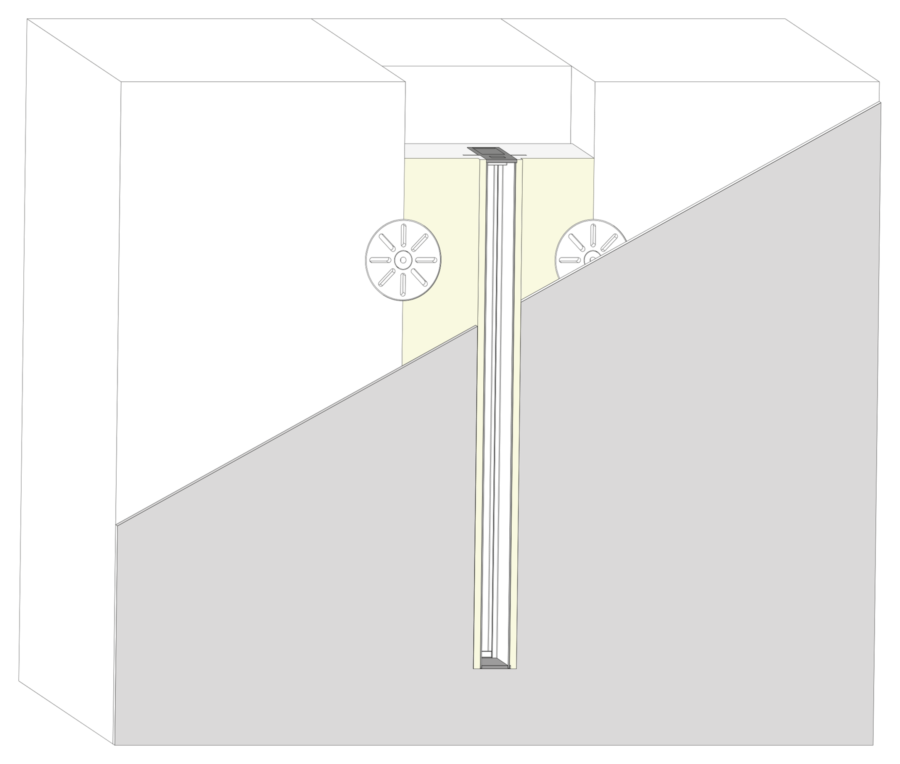
What this solution makes possible.
Pre-formed insulation parts consolidate the connection around the aluminium profile. In the standard version, the profiles are plugged into the insulation board fittings and plastered over. Correct integration into the specific ETICS remains decisive.
Defined fittings for mounting and transformer sections.
Prepared profile area for a continuous light line.
A clear sequence of work from dry fitting to the later light insert.
This is how your line of light is made.
Application, construction and benefits – tailored to your architecture.
Prepare the light housing with a defined fitting
ETICS shaped parts combine the area around the LightLineLed profile in a preformed insulation element. This gives the planned line of light a clearly defined channel within the coordinated facade build-up. The shaped parts can be planned along the desired run and aligned with the later plaster surface. For architecture and execution, the transition between insulation and light profile thus becomes concretely visible even before fitting. This makes it easier to coordinate light run, installation space and surface together.
Combine mounting and technical sections deliberately
Different fitting cross-sections are available for the mounting profile and the deeper driver profile. The mounting area creates the channel for the later luminaire insert; the driver section adds the necessary space for suitable supply technology and connections. The fitting dimensions describe this local profile area and not the entire insulation thickness of the building. Light and technical zones can thus be deliberately arranged, while the remaining insulation and the requirements of the façade build-up are coordinated separately.
Finish the facade, then install the light
In the standard design, the aluminium profiles are inserted into the insulation fittings and integrated into the intended plaster build-up. During this work, the profile opening remains protected. Only after completion does the prepared light unit follow, with the matching visible profile and the desired cover. This separation keeps the lighting components away from plaster and site dirt. With an intended removal route, the suitable insert remains accessible later without having to reopen the entire façade build-up.
A suitable solution for the specific ETICS
The benefit comes from the interplay of shaped part, profile and coordinated facade connection. Installation position, fixing, remaining insulation and weathering are checked together with the ETICS specialist contractor. The standard version has not been tested as a driving-rain-tight system; any additional sealing required is clarified on a project basis. The section drawings show the two shaped-part variants and help with selection. In this way, the desired line of light can be prepared with a defined component area and fitted into the overall facade planning.
The solution in section
The system as construction progresses.
From the prepared housing to the finished light line.
The path to the finished light line
Clarify suitability in advance
Have the installing contractor check the installation position, weathering, substrate, ETICS and connections. Document the detail and any required additional measures.
Cut and fit
Measure component temperatures, mark out the line of light and plaster plane, and dry-fit the fittings. Take technical access and room for movement into account.
Bonding and fixing
Insert using the adhesive intended for insulation material and ETICS, and fix according to the agreed anchor plan. The fitting must not be held by the plaster alone.
Reinforce, plaster and fit
Overlap the connection mesh with the surface mesh by at least 10 cm, unless the system requires a larger overlap. Protect the opening, observe standing times and, once finished, insert the secured light unit.
Installation & documents.
The installation and processing instructions accompany the actual implementation of your line of light.
ETICS fittings · Installation & processing
PDF · matching instructions
Safety and installation notes
PDF · observe together with the instructions
The complete installation manual
All applications and system details
Processing notes in detailMounting clips, safety cable and further notes on the specific design
Build-up details
MPmF with mounting profile: shaped part 125 × 50 mm. TPmF with driver profile: shaped part 125 × 75 mm.
The 50/75 mm describe the fitting, not the entire facade insulation. Check the remaining insulation thickness, thermal bridging and fire behaviour of the overall build-up.
An additionally sealed version is not part of the standard range. Standard profiles and fittings have not been tested for driving-rain tightness, in particular 600 Pa.
Processing and installation
Mounting clips V2 (20 mm) and V3 (30 mm) may be shortened. Afterwards, both side legs must again taper inwards at an angle and form tips like the original tips. Blunt or straight-cut leg ends cause the clips to break when snapping in. Bevel both legs accordingly, deburr the cut points and check the tip shape before installation. Then check for full snap-in seating and secure hold. Do not use damaged clips. No blanket shortening dimension or cutting angle.
An additionally sealed 600 Pa concept is possible on request on a project basis, but is not a confirmed standard certification. Design and required verification are defined in the respective project.
Check profile joints, ends, cable glands, water paths, fixing and installation position before closing, and document for handover.
The retaining clip of the fall protection locks exclusively into the mounting profile, never into the flush-mount driver profile. If the light line begins with 0.5 or 1 m of driver profile, the upper securing fixing lies only in the adjoining mounting profile. A continuous flush-mount driver profile does not allow this type of securing; every lighting element must still be secured.
Four mounting clips per metre, rounded up and at least two per section. V1: 10 mm, V2: 20 mm, V3: 30 mm – choose to match the actual fit-out height. Secure visible profiles at the start, at every joint and at the end; the connector pair sits in both rear longitudinal slots of the suitable visible profile.
In the flush-mount driver profile, maximum driver installation height is 18 mm; remove the pull-out tab only after complete installation. MPW recommends routing the conduit in at the start of the driver profile, not through the end caps. Keep the electronics, terminal point and inspection access accessible.
Outdoor suitability is assessed for the entire detail: weather, condensation, cable entries, terminals, heat dissipation and inspection belong together. IP67/IP68 of individual components is not proof of a driving-rain-tight façade.
Before cutting, measure the temperature of the profile and cover. Allow room for movement at joints and end caps for heating and cooling, and clip in the cover free of stress.
Prepared for your light line.
Molded parts and profile variants for the matching application.
Discover the matching products.
Profiles, covers and accessories together make up your light line. The product pages show versions and matching combinations.
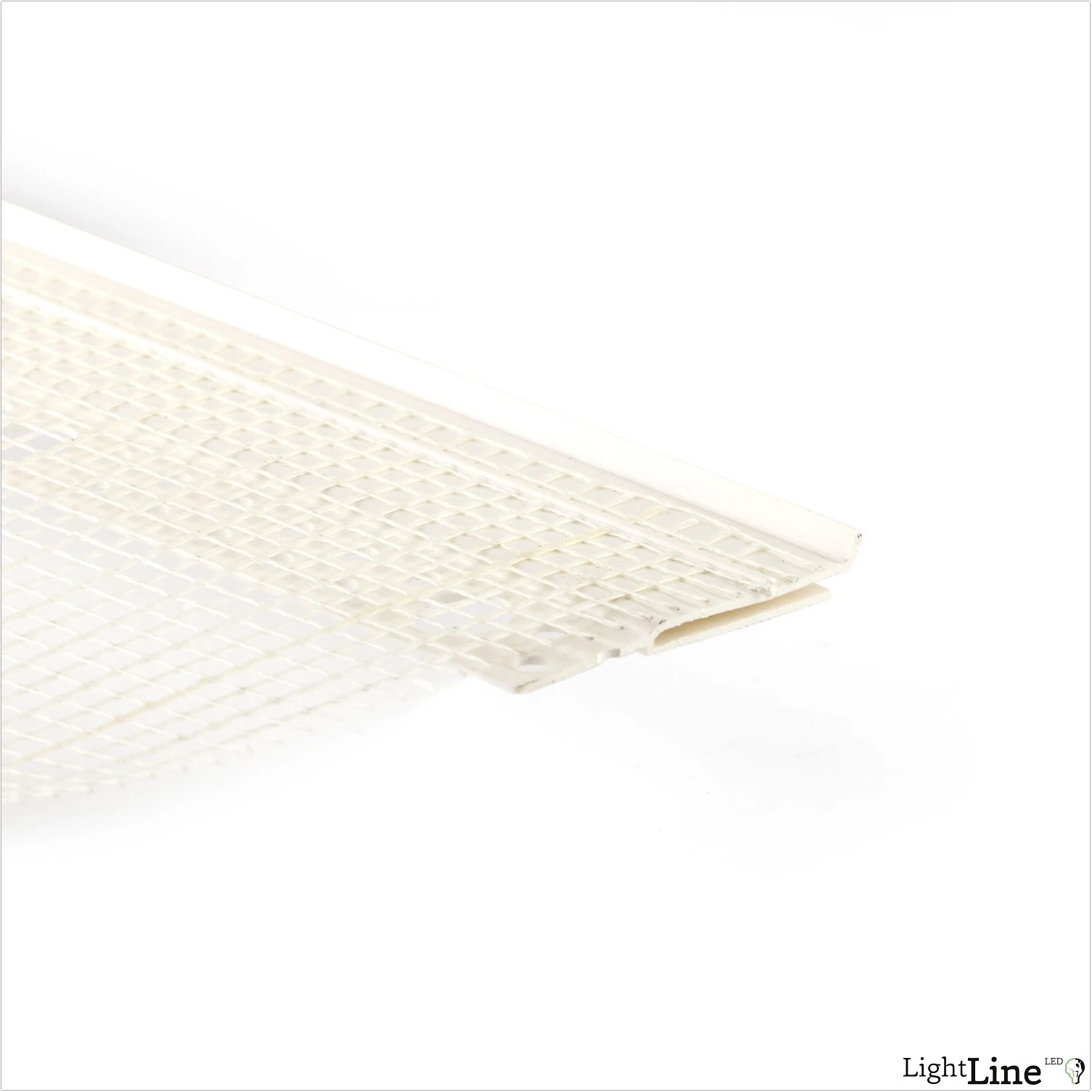
ETICS connection profile with mesh
Transition from the profile to the ETICS build-up
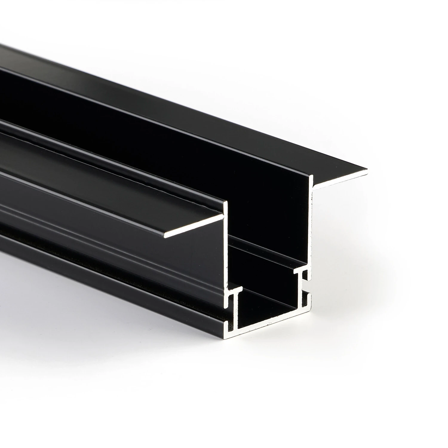
Mounting profile with 3 mm flange
3 mm flange for suitable sheet-metal and façade connections
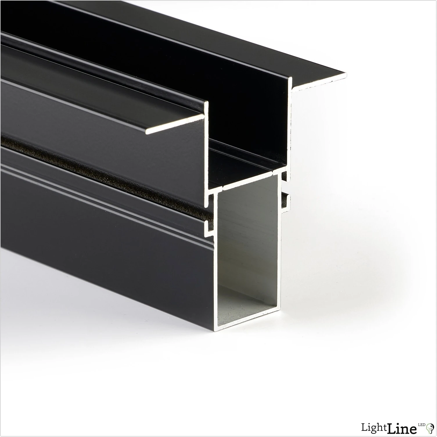
Driver profile with 3 mm wing
Technical space directly behind the facade line of light
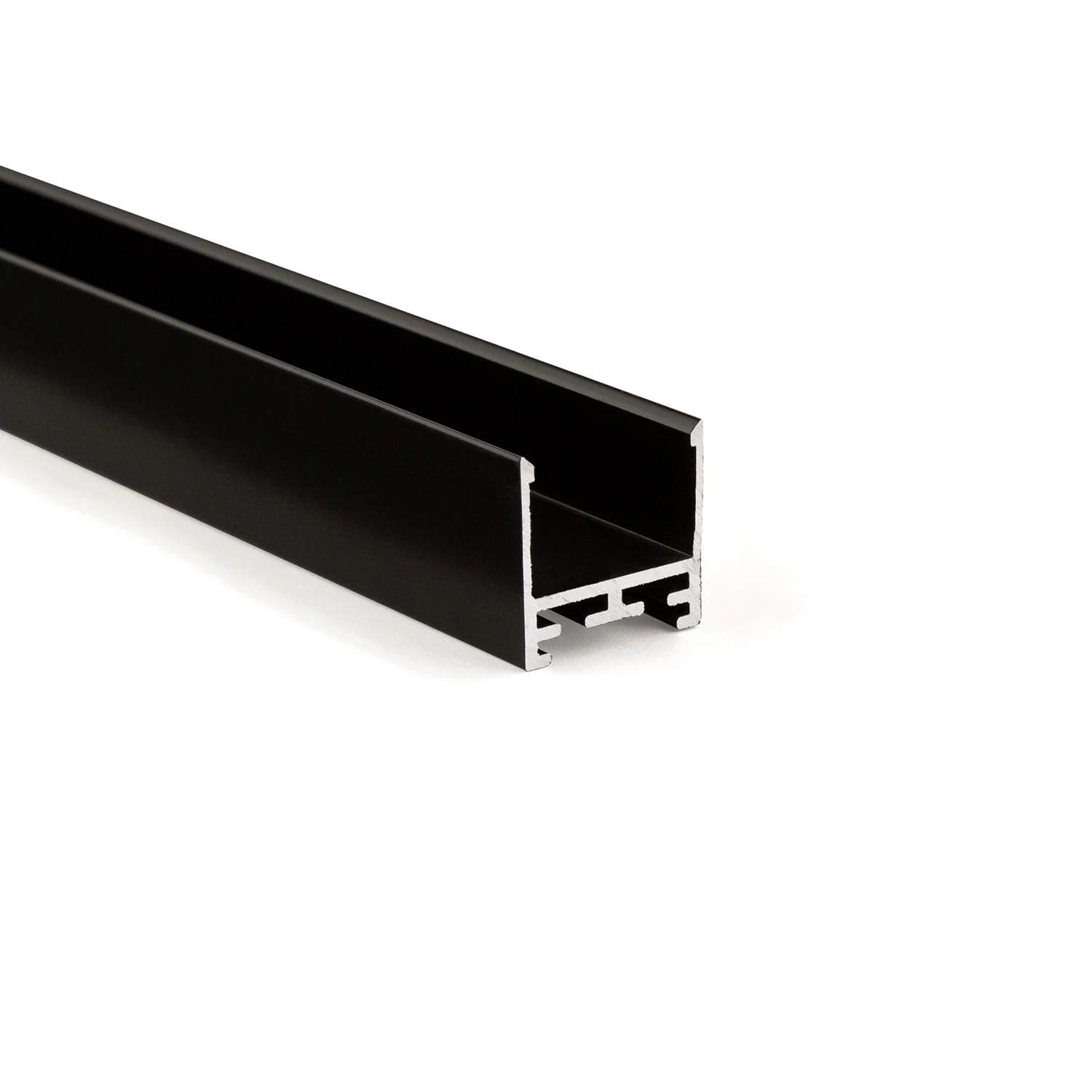
LL25 profile – the all-round visible profile
Consistent design language for recessed, surface-mounted and pendant installations
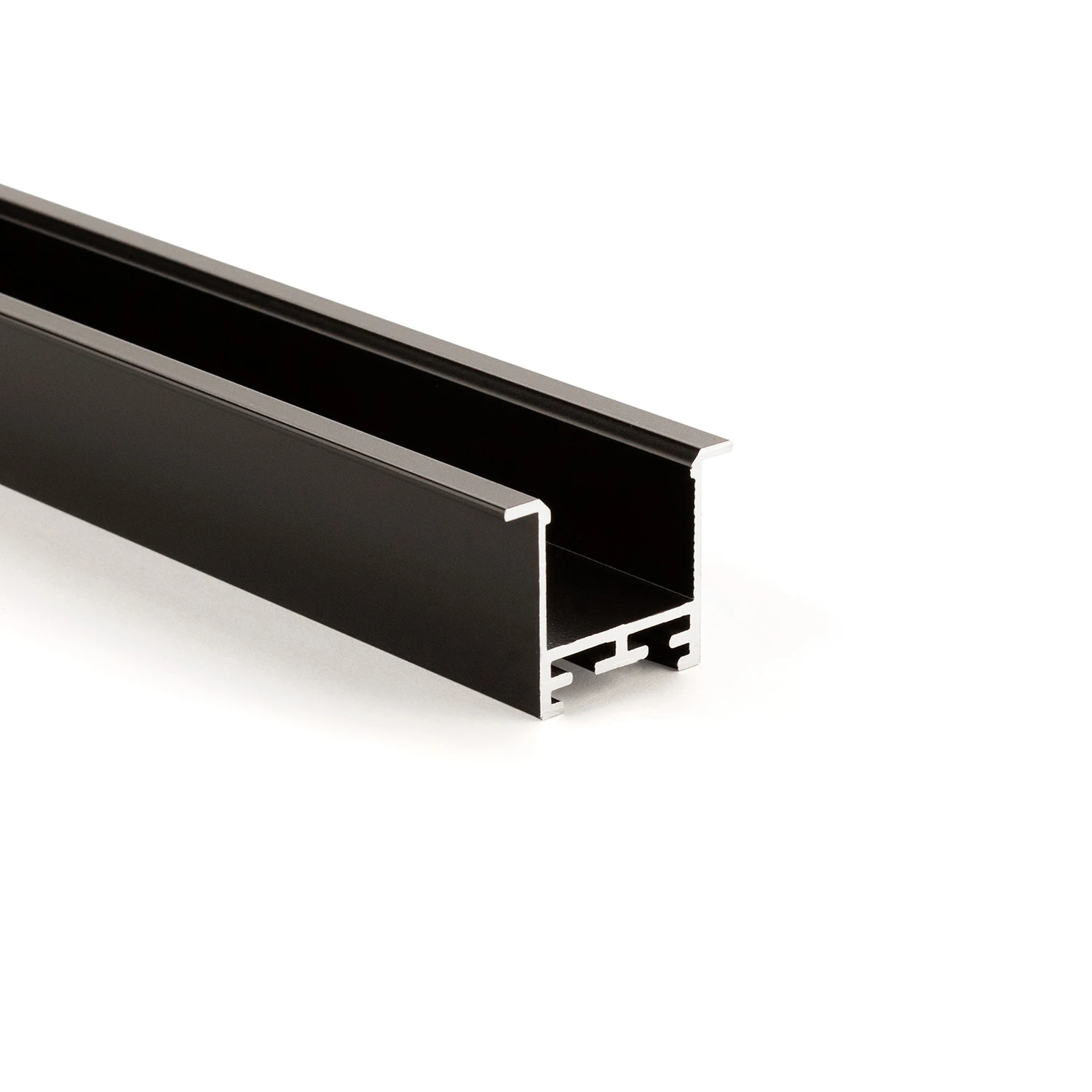
Recessed and visible profile LL35F
Visible aluminium edge covers the connection joint
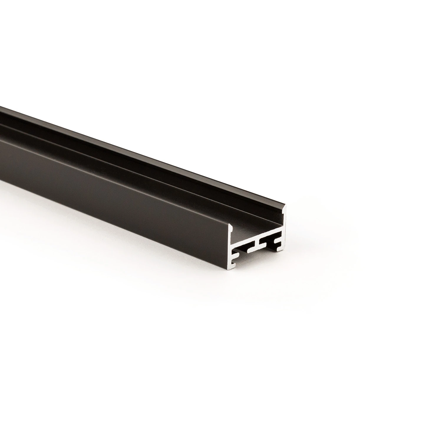
Visible profile LL2515
Compact aluminium body with sculptural V5 cover
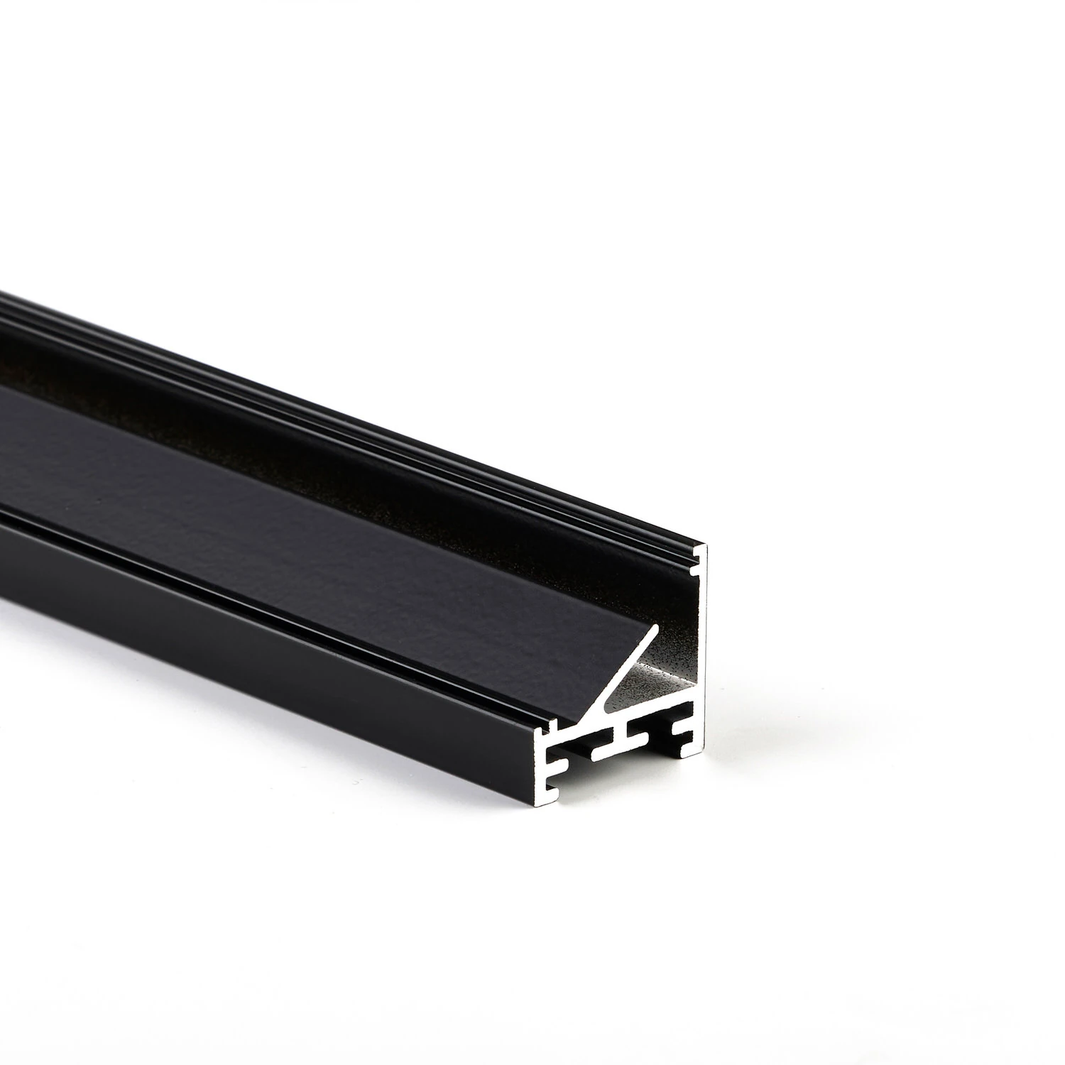
Corner visible profile LL2511E
45° inclined light-emitting surface for targeted aiming
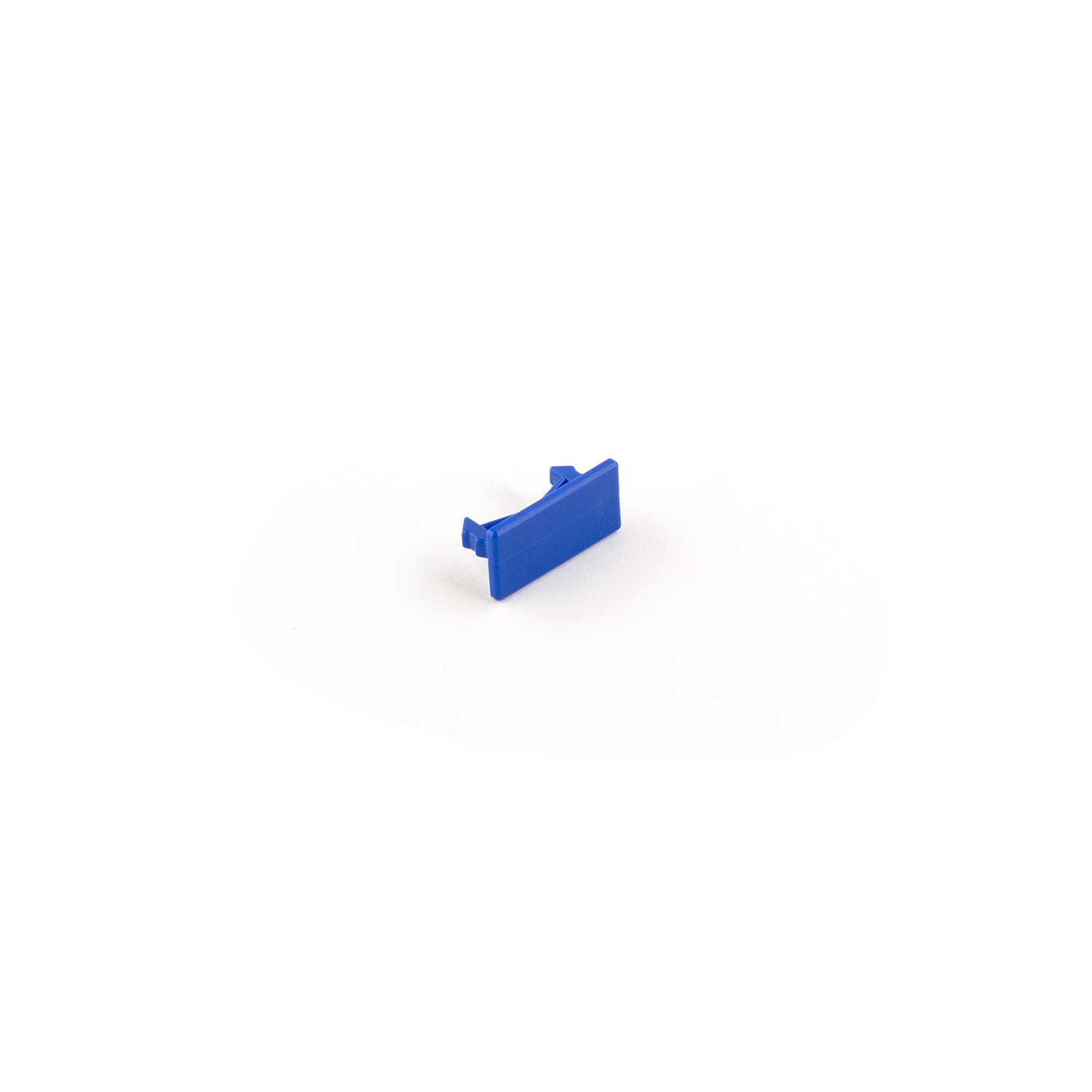
Mounting clips V1, V2 and V3
Height adjustment within the intended combination
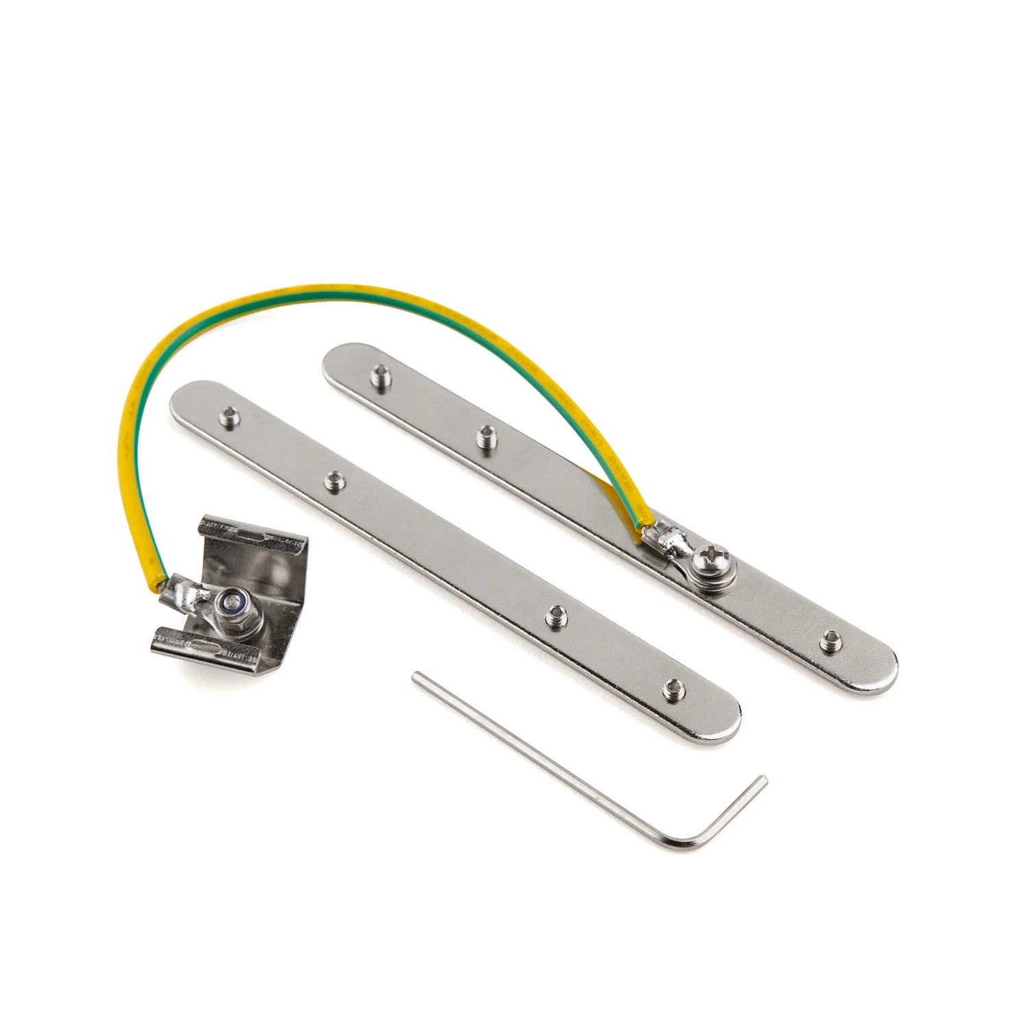
Fall protection for profiles with flange
Connecting and securing at the profile joint
Light line found.
We'll clarify the details together.
Building material, surface and desired lighting effect set the direction. MPW supports you with the right system version and the next steps.
More possibilities for your architecture.
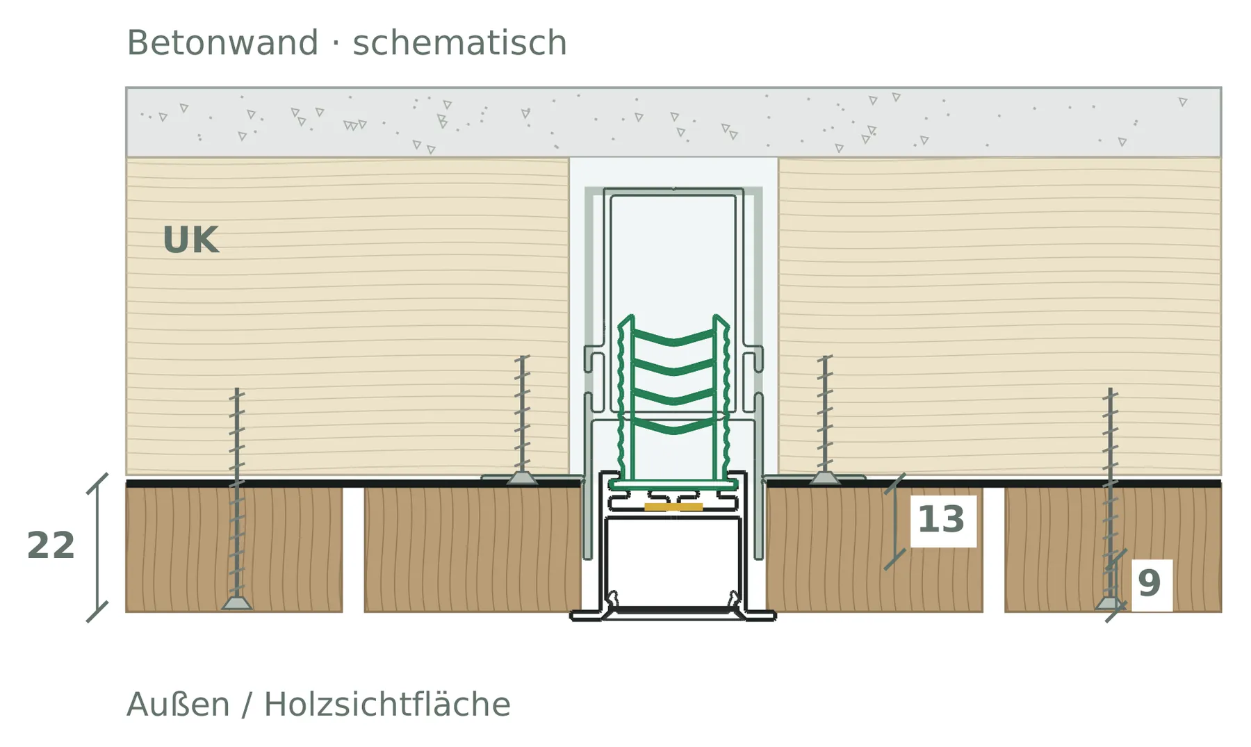 09
Timber facade / ventilated rainscreen
Three ways of installing light in the rainscreen timber façade.
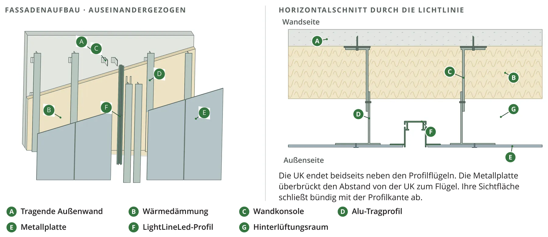 10
Metal facade / ventilated cladding
Profile connection, fixing and material movement in the metal facade build-up.
 11
Plaster-base facade, stone & ceramic
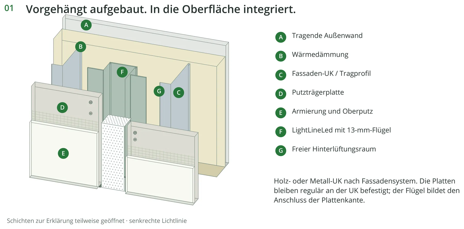
Plaster base boards, stone or ceramic – with a matched visible joint.
Light lines in architecture.
Discover implemented LightLineLed solutions in different rooms and building materials.